Installation 2-15
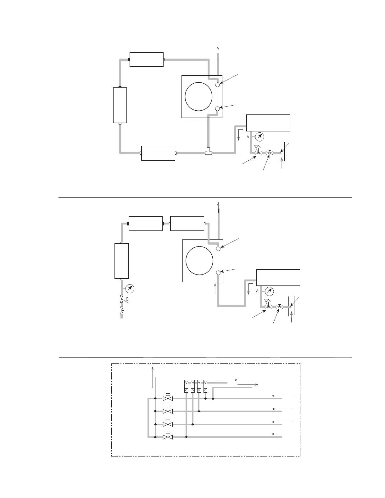
Molecular
Sieve Dryer
(1 to 2 ppm)
Super-activated
Molecular Sieve Dryer
~ 0.1 ppm (Optional)
Contaminant Trap
(Optional)
REFERENCE
SAMPLE
Field
Unit
Probe
Sample Switching
Valves
(See Detail, Figure 9c)
Pressure
Reducer
Main Sample Line
Shutoff Valve
Sample
Source
Vent to
Appropriate
Area
Sample Tap Ball Valve
Not Shown
Reference
Gas Source
Molecular
Sieve Dryer
(1 to 2 ppm)
Contaminant
Trap
(Optional)
REFERENCE
SAMPLE
Field
Unit
Pressure
Reducer
Shutoff
Valve
Super-activated
Molecular Sieve Dryer
~ 0.1 ppm (Optional)
Vent to
Appropriate
Area
Pressure
Reducer
Main Sample Line
Shutoff Valve
Sample
Source
Probe
Sample Switching
Valves
(See Detail, Figure 9c)
Sample Tap Ball Valve
Not Shown
SV1
SV2
SV4
SV3
Sample
Switching
Output Line
To Vent
Bypass Flowmeters
Solenoid Valves
120V or 240V
From Sample Point 1 Pressure Reducer
From Sample Point 2 Pressure Reducer
From Sample Point 3 Pressure Reducer
From Sample Point 4 Pressure Reducer
To Dryer (s)
Pressure
Indicator
Pressure
Indicator
Pressure
Indicator
Figure 9c: Detail of Recommended Sample Switching Configuration
Figure 9a: Sample System Using Conditioned Sample Gas as Reference
Figure 9b: Sample System Using Separate Gas Source as Reference
 Loading...