Operation 3-13
Upper limits corre-
spond to output of 20
Output_1_Low The upper limit on the low range of
output 1.
Output_1_Hi The upper limit on the high range of output 1.
Output_X The upper limit of output channel X where X
= 2Õ4.
Offset_1_Low The lower limit on the low range of output 1.
Offset_1_Hi The lower limit on the high range of output 1.
Offset_2 The lower limit of output channel X where X
= 2Õ4.
Lower limits corre-
spond to output of
4 mA. Limits are nor-
mally zero but may also
be positive or negative
values
Range Select-Out1 View and/or alter current analog range (high or low) on output channel 1.
• Press Cancel to return to Analog Range menu without changing the range.
• Press Enter to toggle between low and high range; press Cancel to accept
the displayed range and return to normal operation screen.
View Range Limits View upper (output) and lower (offset) setpoints for both high and low output
ranges on channel 1 and channel 2 output range. Use up and down arrow
keys to highlight setpoint to view; press Enter to display current value.
Alter Range Limits Alter upper (output) and lower (offset) setpoints for channel 1 (both high and
low ranges) and channel 2, 3, and 4 analog outputs. Use
UP AND DOWN ARROW
keys to highlight setpoint to alter; press
ENTER to display current value. Use
NUMBER KEYS to enter new value; press ENTER to load the change and return
to the Analog Range menu. Note that the units associated with these values
correspond to the data on the signal; refer to Page 4-2: Alarm Flags for the
various flags and units.
Setpoints to be viewed and/or altered are:
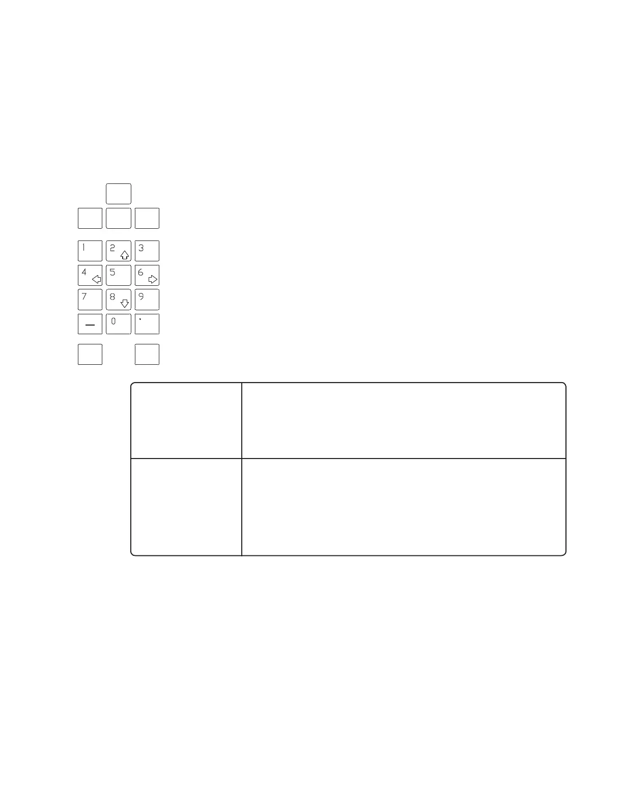
Test/Config Key
All system configuration parameters, both critical (system constants and variables,
calculation coefficients, configuration flags, etc.) and non-critical (time of day, date,
etc.), are accessed through the
TEST/CONFIG key. When the TEST/CONFIG key is pressed,
a password (level 1, 2, or 3) will be required immediately. If the Level 1 password has
been entered, a higher level password will be needed to select Configure Menu. The
menu accessed when Configure Menu is chosen will be different depending on which
password, Level 2 or Level 3, has been entered.
• View Configuration
Selecting this menu item allows software configuration values to be viewed only. It is recommended
that system parameters be recorded periodically so that configuration can be reconstructed in the
event of a computer memory failure. Current software configuration should also be compared
periodically to the factory software configuration data sheet to verify that critical system values
CANCEL
ENTER
ANALOG
RANGE
 Loading...