Service and Parts 7-7
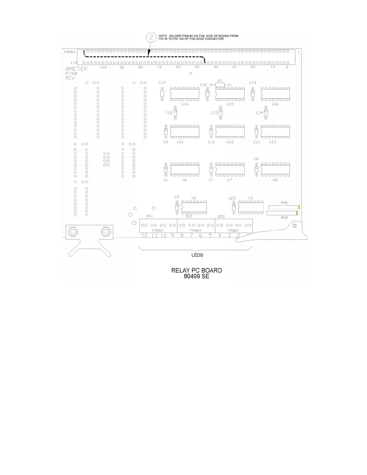
LEDs
LED 1 = Indicates active sample point
LED 2 = Indicates active sample point
LED 3 = Indicates active sample point
LED 4 = Indicates active sample point
LED 5 = Sample Reference - When the light is ON, System is in Reference cycle. When OFF, System is
in Sample cycle.
LED 6 = Calibrate - When the light is ON, the Moisture Generator is off. When the light is OFF, the
Moisture Generator is on for period of Cal Cycle or however long it is left on manually.
LED 7 and LED 8 = Not Used
LED 9 = Not Used
LED 10 = System Alarm - Indicates alarm activation
LED 11 = Range ID - Indicates alert activation
LED12 = Not Used
 Loading...