3-10 | Model 900 ADA / Model 930 Sulfur Pit Analyzers
4. Install the Measuring Cell in the Analyzer Oven:
a. Swing the Optical Bench toward the Electronics Enclosure and
then swing the Measuring Cell toward the Oven (Figure 3-5).
Align the hole in the Heat Transfer Block with the Cell RTD tip
(on Heater Plate) and carefully push the Measuring Cell toward
the Heater Plate. Adjust the entire Measuring Cell/Optical Bench
Assembly as required to firmly seat the Measuring Cell against the
Heater Plate.
Using a flat hex key, insert the M4 x 25 screw into the counter bore
hole in the Heat Transfer Block and thread it onto the Cell RTD
(until it is snug). Do not use a ball driver. Do not tighten the screw
at this time.
IMPORTANT
Positioning of the Heat Transfer Block in the Oven is critical.
Improper positioning of the Heat Transfer Block can result in:
• Poor contact between the Cell RTD tip and the Heat Transfer Block.
• Poor alignment of the Cell Extension seal in the Oven and
Electronics Enclosure cabinets.
NOTE
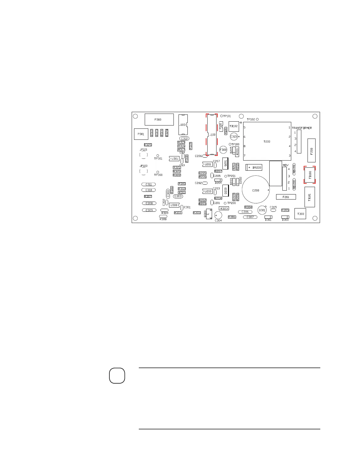
3. Connect Optical Bench wiring:
a. Ribbon cable from J102 on Micro-Interface board to J100 on Optical
Bench board.
b. AC power line (connector plug) to TB100 on Optical Bench board.
c. Using the disconnect terminals, connect the yellow/green ground
wire from the Electronics Enclosure to the yellow/green ground
wire from the Optical Bench.
Figure 3-3.
Optical Bench board
layout.
 Loading...