4
IOM (Safety) - Installation, Operation and Maintenance
Optical Oxygen Analyzer
LIST OF FIGURES 4
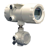
Figure 1 - OXYvisor overview of hardware features 8
Figure 2 - OXYvisor Overall Dimensions 8
Figure 3 - OXYvisor Product Label / Name Plate 10
Figure 4 - OXYvisor Declaration of Conformity 11
Figure 5 - OXYvisor Vertical Pipe Mount Examples 13
Figure 6 - OXYvisor Horizontal Pipe Mount Example 13
Figure 7 - OXYvisor Protective Ground Screws 13
Figure 8 - AC Terminal Board - Located in Rear (Wiring) Compartment 14
Figure 9- DC Terminal Board - Located in Rear (Wiring) Compartment 14
Figure 10 - BOS Sensor With Integral RTD Through Junction Box 15
Figure 12 - BOS Sensor And External RTD or Zone 1 15
Figure 11 - BOS Sensor And External RTD through Junction Box 15
Figure 13.1 - Zone 1 HazLoc - Installation Control DWG - 2P0345 (p.1) 16
Figure 13.2 - Zone 1 HazLoc - Installation Control DWG - 2P0345 (p.2) 16
Figure 13.3 - Zone 1 HazLoc - Installation Control DWG - 2P0345 (p.3) 17
Figure 14.1 - Zone 2 HazLoc - Installation Control DWG - 2P0346 (p.1) 17
Figure 14.2 - Zone 2 HazLoc - Installation Control DWG - 2P0346 (p.2) 18
Figure 14.3 - Zone 2 HazLoc - Installation Control DWG - 2P0346 (p.3) 18
Figure 15.1 - Class I Div. 2 HazLoc - Installation Control DWG - 2P0335 (p.1) 19
Figure 15.2 - Class I Div. 2 HazLoc - Installation Control DWG - 2P0335 (p.2) 19
Figure 15.3 - Class I Div.2 HazLoc - Installation Control DWG - 2P0335 (p.3) 20
LIST OF TABLES 4
Table 1 - OXYvisor
Table 2 - OXYvisor
Table 3 - OXYvisor
Table 4 - OXYvisor
LIST OF TABLES
LIST OF FIGURES

 Loading...


