Version 15-02-2023 BG 65 dMove / BG 66 dMove Page/Seite 45 / 54
6.8 CANopen-Feldbusanschluss
(nur für CO Versionen)
Die CANopen Schnittstelle und die verwendeten Steck-
verbinder entsprechen dem CiA 303-1-Standard. In
diesem Standard finden Sie alle notwendigen Hinweise
bezüglich Verdrahtung, Topologie und Leitungslängen. Die
Belegung und Funktion entsprechen dem CiA Standard
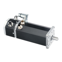
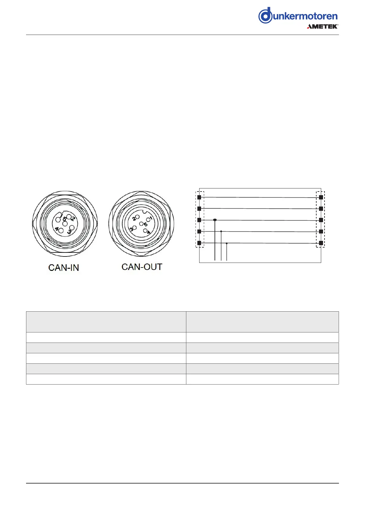
„5-pin micro style connector“. Die zwei 5-poligen Motor-
stecker dienen als Schnittstelle zum CAN-Bus. Der Ste-
cker als CAN-Eingang und die Buchse als CAN-Ausgang.
Die Anbindung des Kabel-Schirms an das Motorgehäuse
muss über die Stecker-Verschraubung erfolgen.
Rundstecker M12 nach DIN EN 61076-2-101
1
2
3
4
5
1
2
3
4
5
To motor electronics /
zur Motorelektronik
CAN in
CAN out
Internal interconnec�on CAN connectors
Interne Verschaltung CAN Stecker
6.8 CANopen Fieldbus Connection
(only for CO versions)
The CANopen interface and the connectors used corre-
spond to the CiA 303-1-standard. This standard contains
all notes necessary for wiring, topology and cable lengths.
Occupation and function correspond to the CiA stan-
dard „5-pin micro style connector“. The two 5-pin motor
connectors serve as interfaces with the CAN bus. The
connector as CAN input and the bush as CAN output.
The cable shield must be connected to the motor housing
via the plug screw connection (e.g. union nut).
Round connector M12 in accordance with DIN EN
61076-2-101
Plug pin/
Stecker Pin
Connection/
Anschluss
1 N. C.
2 N. C.
3 GND
CAN
(optional)
4 CAN-High
5 CAN-Low
 Loading...