123200 03 26-03-2004 35
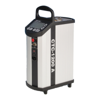
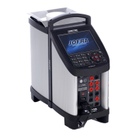
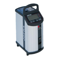
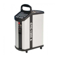
3.3.3 POWER PCB CTC-320/650 A/B, CTC-1200 A, MTC-
320/650 A
The POWER PCB must be adjusted if the POWER PCB or the
CONTROLLER PCB have been replaced.
Necessary equipment
Voltmeter to ensure that the mains voltage is 115V ± 5V or
230V±10V. If the mains voltage falls outside this range, a
variotransformer must be used to generate the correct mains voltage.
Adjustment
c
Switch off the calibrator using the power control switch.
d
Turn the present potentiometer R37 (R26 for CTC-1200 A)
counter clockwise as far as it will go. Then turn the
potentiometer R37 (R26 for CTC-1200 A) clockwise 15 times.
e
Hold down the
key while turning on the calibrator using
the control switch. Release
once the calibration date
is displayed.
f
Set the calibrator to max. temperature (320°C, 650°C or
1200°C) and press
.
g
Instead of the SET temperature, the display will show a figure
which is updated every 2.6 seconds.
h
Turn R37 (R26 for CTC-1200 A) clockwise until the figure
reads between 95.0 and 97.5.
7
Switch off the calibrator using the power control switch.
 Loading...