EasyManuals Logo

Ametek JOFRA CTC-140 A Service Manual

Ametek JOFRA CTC-140 A
54 pages
To Next Page IconTo Next Page
To Previous Page IconTo Previous Page
Page #33 background imageLoading...
Page #33 background image
123200 03 26-03-2004 33
3.3 Adjusting and testing PCBs
3.3.1 CONTROLLER PCB
The CONTROLLER PCB must be adjusted if it has been replaced.
Adjustment
c
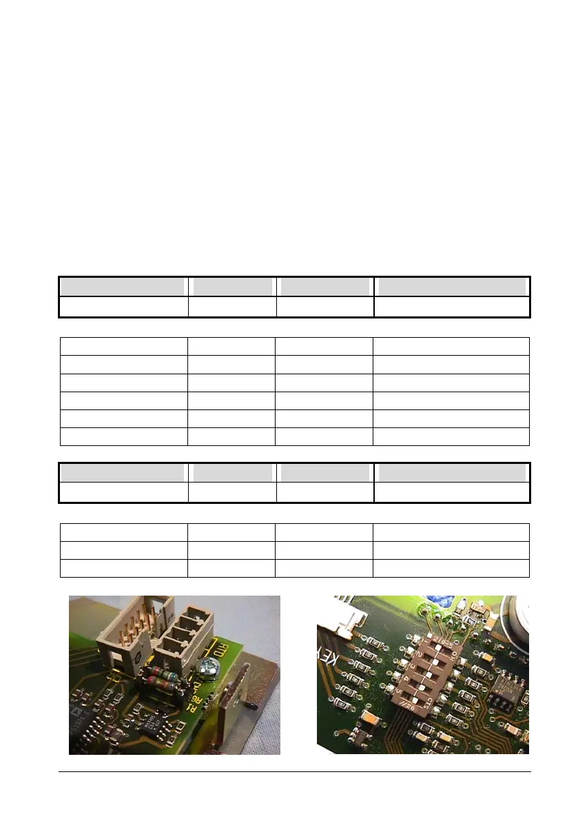
Set up the dipswitch and solder the resistors R1 and R6 with
values as shown in the table.
Dipswitch 1 = ON
Model R1 R6 S1 (Dipswitch)
CTC
1 2 3 4 5
140 A 487R 4K64 1 1 1 0 1
320 A 487R 4K64 0 1 1 0 1
320 B 487R 4K64 1 0 1 0 1
650 A 73R2 698R 0 0 1 0 1
650 B 73R2 698R 1 1 0 0 1
1200 A - - 1 0 1 1 0
Model R1 R6 S1 (Dipswitch)
MTC
1 2 3 4 5
140 A 487R 4K64 0 1 0 0 1
320 A 487R 4K64 1 0 0 0 1
650 A 73R2 698R 1 1 1 1 0

Other manuals for Ametek JOFRA CTC-140 A

Questions and Answers:

Question and Answer IconNeed help?

Do you have a question about the Ametek JOFRA CTC-140 A and is the answer not in the manual?

Ametek JOFRA CTC-140 A Specifications

General IconGeneral
BrandAmetek
ModelJOFRA CTC-140 A
CategoryMeasuring Instruments
LanguageEnglish

Related product manuals