123200 03 26-03-2004 25
3.2 Replacement of spare parts
See exploded views in Chapter 4.0.
Caution…
Remember to disconnect the instrument from the mains
supply before it is dismantled.
Necessary tools:
• Wire cutter
• Screw drivers
• 7 mm wrench
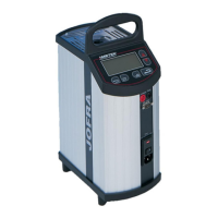
A. Removal of display and keyboard unit (exploded views,
pos. 1)
1. Remove the 2 screws (pos. 2) mounted at an angle
through the handle of the top frame.
2. Ensure that you also remove the washers beneath the
screws.
3. Lift the unit by carefully loosening it with a small
screwdriver near the handle of the top frame.
4. To remove the unit completely, disconnect the 3 wires:
The 16 circuit ribbon cable (pos. 3), the 10 circuit ribbon
cable (pos. 4) and the reference sensor wire ending in a
4-poled connector (pos. 5).
The top frame must be removed if further replacements are
necessary.
B. Removal of top frame (exploded views, pos. 6)
1. Remove the grid plate (pos. 7) by removing the 3 screws
(pos. 8) holding it in place.
2. Remove the 5 screws now accessible (pos. 9) holding
the top frame.
3. Ensure that you also remove the washers beneath the
screws.
 Loading...
