26 26-03-2004 123200 03
4. The top frame can now be removed entirely to render the
interior of the instrument accessible.
C. Removal of Power PCB
(Section 4.2, exploded view -
CTC-140 A, MTC-140 A)
1. Disconnect the 3 cables on the Power PCB which run to
the fan (pos. 10), the Peltier elements (pos. 11) and the
transformer (pos. 12).
2. It is now possible to retract the Power PCB (pos. 13)
from the instrument.
(Section 4.3, 4.4 exploded views - CTC-320/650 A, MTC-
320/650 A
)
1. Disconnect the 4 cables from the heating elements (8
poled connector) (pos. 10), from the power inlet (4 poled
connector) (pos. 11) from the thermocoupler (2 poled
connector) (pos. 12) and from the fan (pos. 13).
2. It is now possible to retract the Power PCB (pos. 14)
from the instrument.
(Section 4.5, 4.6 exploded views -
CTC-320 B, CTC-650 B)
1. Remove the support plate (pos. 23) by pulling it up.
2. Disconnect the 3 cables from the heating elements (8
poled connector) (pos. 10), from the power inlet (4 poled
connector) (pos. 11) and from the fan (2 poled connector)
(pos. 12).
3. It is now possible to retract the Power PCB (pos. 13)
from the instrument.
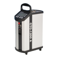
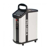
(Section 4.7 exploded view -
CTC-1200 A)
1. Disconnect the 4 cables from the heating elements (4
poled connector) (pos. 10), from the transformer (6 poled
connector) (pos. 11) from the thermocoupler (2 poled
connector) (pos. 5B) and from the fan (pos. 12).
2. It is now possible to retract the Power PCB (pos. 13)
from the instrument.
Note…
If the Power PCB has been replaced, you must adjust the
new PCB in accordance with section 3.3.
 Loading...