Installation Manual - Rev D California Instruments
MX Series 14
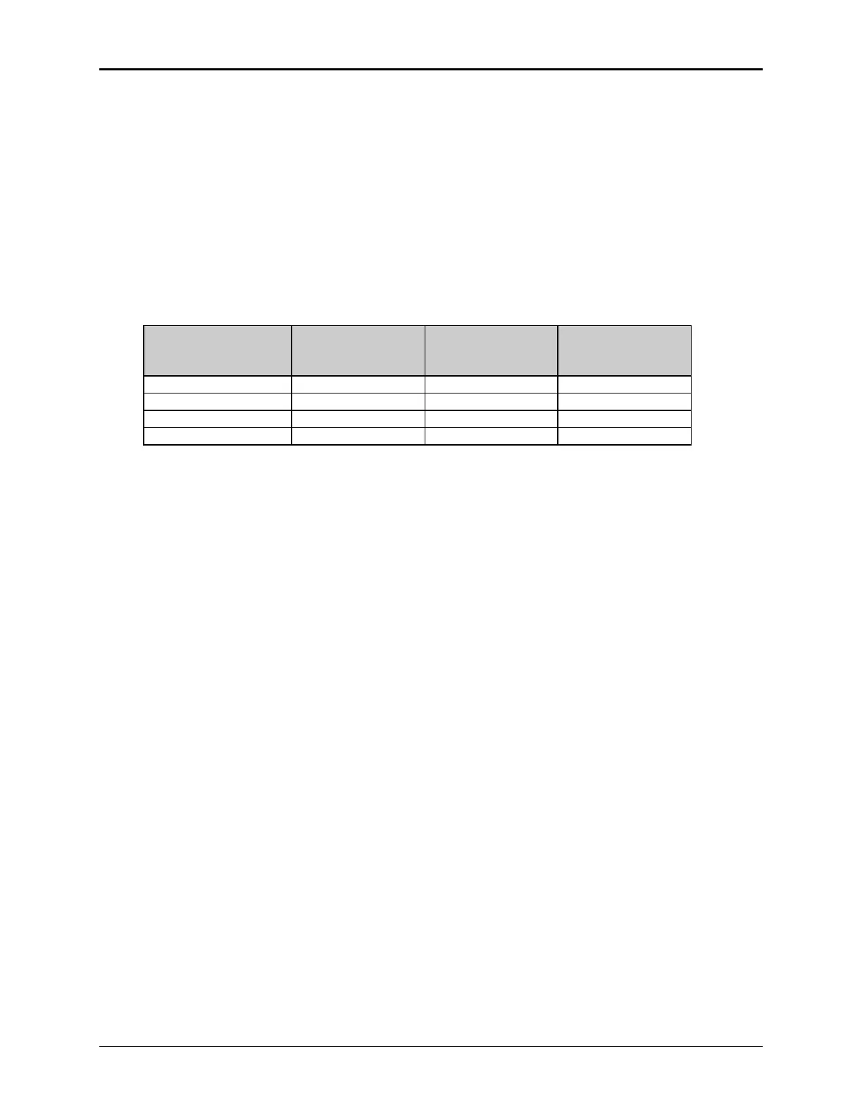
The output power cables must be large enough to prevent a total voltage drop exceeding 1% of
the rated output voltage between the power source and the load. Table 2-2 shows the size of the
cables that may be used. Note that wires must be sized to accommodate the maximum current
that is available. This may be a function of the voltage range and phase mode on some MX45
models. If the MX45 has more than one output voltage range, size the wires for the lowest
available voltage range as the currents will be highest in that range.
Cable lengths must not exceed twenty-five (25) feet. For lengths greater than 25 feet, calculate
the voltage drop from the following formula:
2 X DISTANCE X CABLE RESISTANCE PER FT. X CURRENT = VOLT DROP
Table 2-2: Suggested Output Wiring Sizes
 Loading...


