Installation Manual - Rev D California Instruments
MX Series 5
Table of Contents
1. Introduction ..................................................................................................................................... 6
1.1 General Description ................................................................................................................................ 6
1.2 Manual organization and format ............................................................................................................. 6
2. Unpacking and Installation ............................................................................................................. 7
2.1 Unpacking ............................................................................................................................................... 7
2.2 Power Requirements .............................................................................................................................. 7
2.3 Mechanical Installation............................................................................................................................ 8
2.4 AC Input Connections and Wiring ........................................................................................................... 8
2.5 AC On/Off Circuit Breaker on MX45 front panel. .................................................................................. 11
2.6 Output Connections .............................................................................................................................. 13
2.7 Connectors - Rear Panel ...................................................................................................................... 23
2.8 Multiple Cabinet System Configurations ............................................................................................... 26
2.9 Clock and Lock Configurations ............................................................................................................. 27
2.10 Basic Initial Functional Test .................................................................................................................. 29
List of Figures
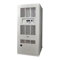
Figure 2-1: The MX45 Power Source .................................................................................................................... 7
Figure 2-2: Location of AC Input Fuse Block and Chassis Ground Connection .................................................... 9
Figure 2-3: MX45 AC Input Connection Diagram ................................................................................................ 10
Figure 2-4: Rear Panel ........................................................................................................................................ 12
Figure 2-5: External sense cable shield connection to chassis ground ............................................................... 13
Figure 2-6: Location of Output Terminals ............................................................................................................ 15
Figure 2-7: MX45-1 Output Wiring ...................................................................................................................... 16
Figure 2-8: MX45-3 Output Wiring ...................................................................................................................... 17
Figure 2-9: MX90 or MX90-MB Output Wiring..................................................................................................... 18
Figure 2-10: Two MX45's in Clock and Lock mode Output Wiring ...................................................................... 19
Figure 2-11: MX135 or MX135-MB Output Wiring............................................................................................... 20
Figure 2-12: Three MX45's in Clock and Lock mode - Output Wiring ................................................................. 21
Figure 2-13: Ship kit Terminal Block dimensions ................................................................................................ 22
Figure 2-14: Emergency Switch (ES Option) shut off inter connect on -MB systems. ......................................... 25
Figure 2-14: Multi-Cabinet DIP Switch Location and Setting ............................................................................... 26
Figure 2-15: Functional Test Setup. .................................................................................................................... 30
List of Tables
Table 2-1: Suggested Input Wiring Sizes for each MX45 Cabinet....................................................................... 11
Table 2-2: Suggested Output Wiring Sizes ......................................................................................................... 14
Table 2-3: Output Terminal connections. ............................................................................................................ 15
Table 2-4: System Interface Connectors ............................................................................................................. 23
Table 2-5: Analog Interface Connector ............................................................................................................... 24
Table 2-6: BNC Connectors ................................................................................................................................ 24
Table 2-7: External Sense Connector ................................................................................................................. 25
Table 2-8: Clock and Lock Configuration settings ............................................................................................... 27
Table 2-9: Clock and Lock Initialization settings ................................................................................................. 28
 Loading...


