Installation Manual - Rev D California Instruments
MX Series 24
300 VRNG: 300 V AC Range Select
COM: Common. Signal return.
/REM OFF: Remote Off Control not
COM: Common. Signal return
FLK/BYP: Flicker / Bypass OMNI control
CLA: Current Limit A. Programmed current limit reference for phase A
CLC: Current Limit C. Programmed current limit reference for phase C
CSB: Current Sum Phase B.
FLT B: Amplifier Fault Phase B
INP OFF: Input power control
A ERR HI: Error Signal Phase A, high
B ERR LO: Error Signal Phase B, low
C ERR HI: Error Signal Phase C, high
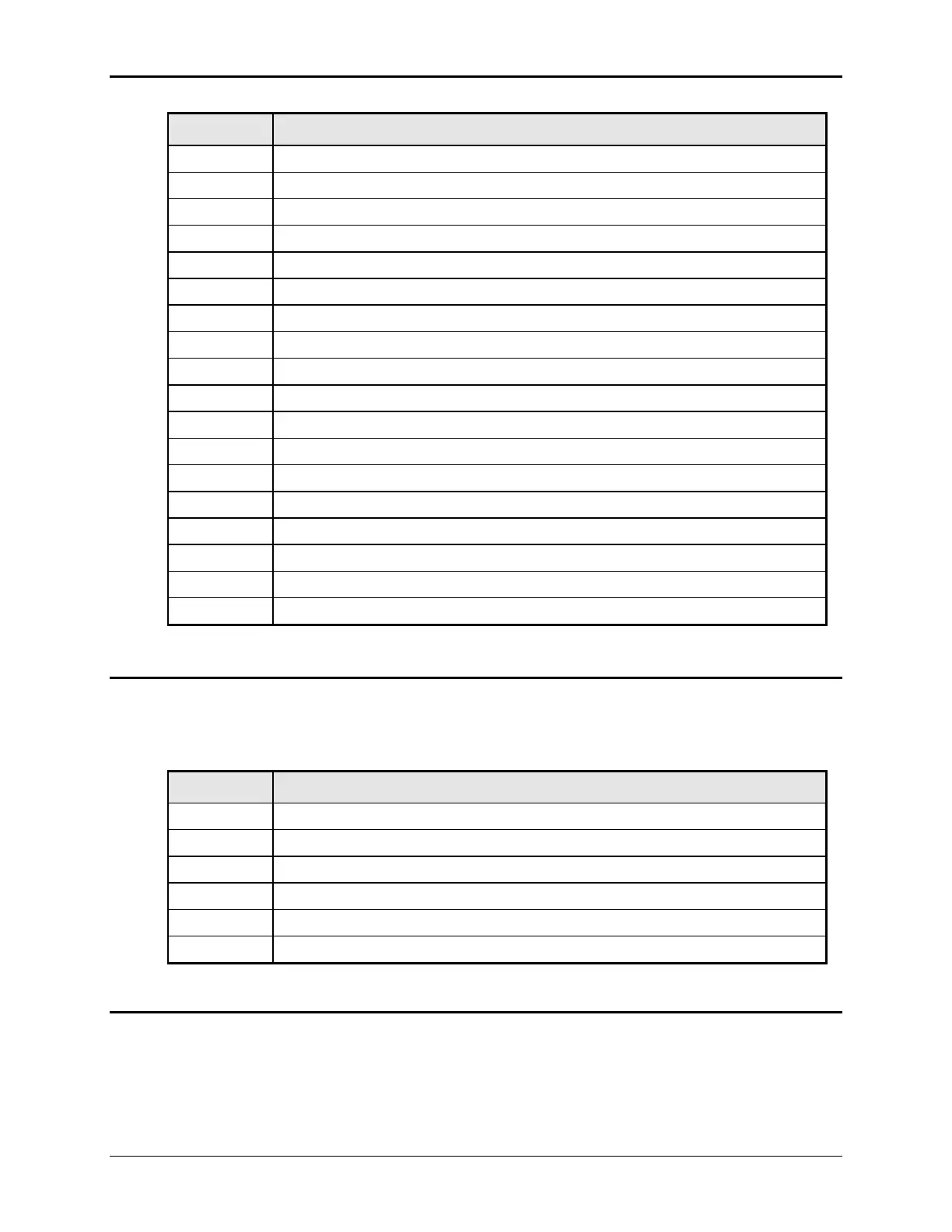
2.7.2 Analog Input Connector
Input screw-terminal strip. Functions are called out on rear panel decal. Table shows connections
from left to right when standing at the rear of the MX cabinet.
Table 2-5: Analog Interface Connector
RPV HI. INPUT: Analog input for External Modulation
EXT SYNC HI INPUT: Analog input for external sync mode.
EXT SYNC Lo INPUT: return.
RI: INPUT: Remote Inhibit. (Contact closure).
2.7.3 BNC Connectors
BNC connectors. Functions are called out on rear panel decal. Table shows connections from left
to right when standing at the rear of the MX cabinet.
Table 2-6: BNC Connectors

 Loading...


