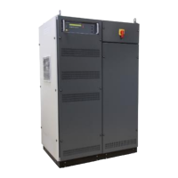
1 Ventilator controller part
2 Framebus IN / OUT
3 Serial from DPA 500N / 503
4 Trigger IN1 / IN2
5 Trigger OUT1 / OUT2
6 Ethernet port
7 USB port
8 DUT monitor
9 GPIB / IEEE 488 port
10 Heat Sink air output
11 Ventilator ( output)
12 Safety circuit
13 Fuse 3.15 A slow blow ( ctrl)
14 Mains in CEE 32 A 3x400 V
15 Sense input
16 Test supply output
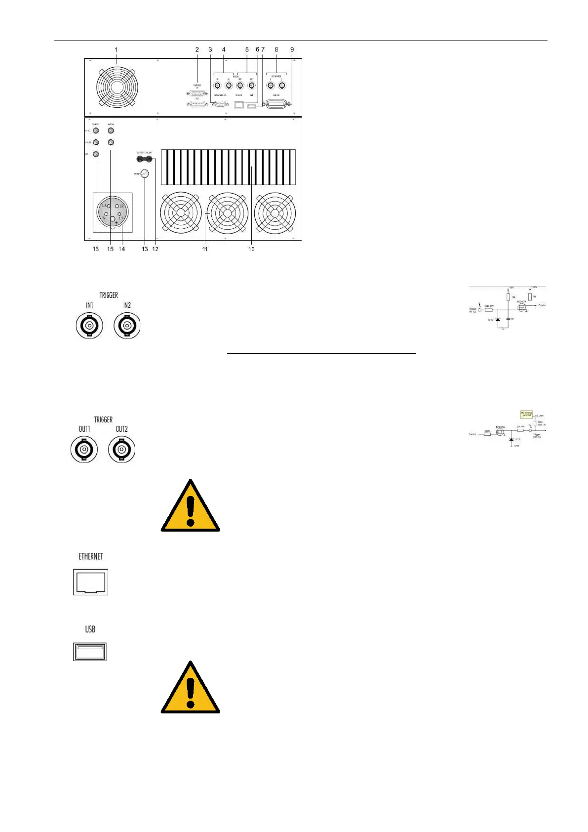
Trigger input for event triggering. This trigger inputs
are connected directly to the DSP signal processor.
Input Signal : Negative slope
Input Function Remarks
Trigger IN 1 : Wave start
Trigger IN 2 : Wave stop
Trigger output for event triggering. This trigger
outputs are generated from the DSP signal
processor.
Max. voltage: 24 V ( pull up )
Current : 100 mA
NOTE : For use the trigger out the user must connect
an external DC source for pull up the trigger
signal. If no external dc source is available, a
T-connection to Trigger IN will deliver the dc
signal.
The network controller supports a 10 / 100Base-
Tinterface. The device auto-negotiates the use of a
10 Mbit/sec or 100 Mbit/sec connection.
Pin assignment
1: TXD+
2: TXD
3: RXD+
4: RXD-
USB port for data transfer to or from a memory stick.
The power contacts for USB devices are not protected. They are
suitable to supply connected USB devices with a maximum of 500
mA power dissipation. Don’t supply external USB devices with
higher power dissipation through this interface.
Pin assignment
1: GND
2: +DATA
3: -DATA
4: VCC
 Loading...