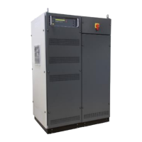
1 Ventilator controller part
2 Framebus IN / OUT
3 Serial from DPA 500N / 503
4 Trigger IN1 / IN2
5 Trigger OUT1 / OUT2
6 Ethernet port
7 USB port
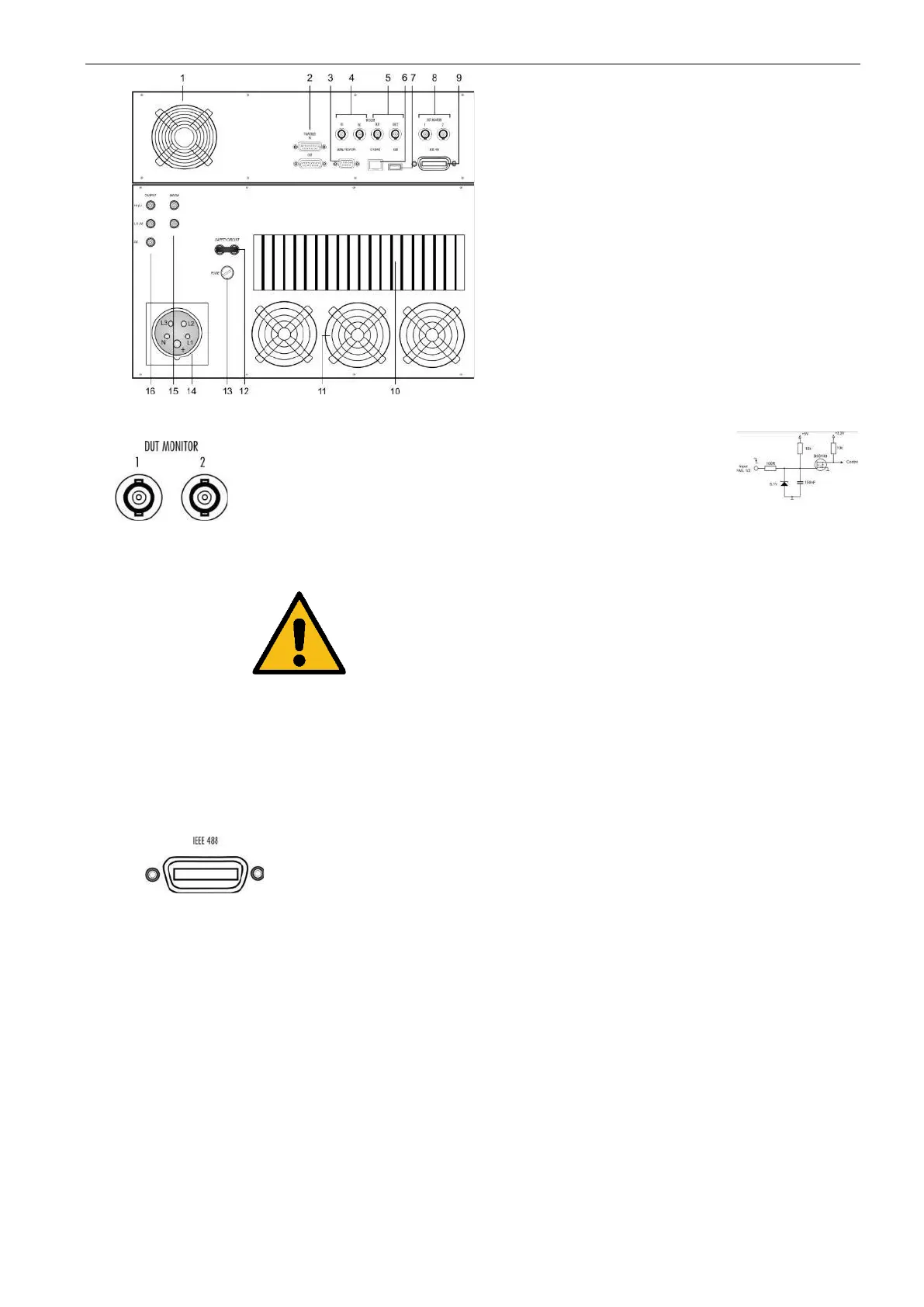
8 DUT monitor
9 GPIB / IEEE 488 port
10 Heat Sink air output
11 Ventilator ( output)
12 Safety circuit
13 Fuse 3.15 A slow blow ( ctrl)
14 Mains in CEE 32 A 3x400 V
15 Sense input
16 Test supply output
DUT monitor for any fail detection.
DUT Monitor 1:
DUT Monitor 2:
Function:
Input signal: Negative slope.
NOTE: The signal must be released to high before
you start the next wave. The test will start
and does not stop if the monitor signal is at
low level during the wave start
Settings
The DUT monitor is settable in the NetWave software
and has the following function
Disabled no function
Stop stops immediately the wave
Notify send a message to DUT Log file
Parallel interface GPIB / IEEE 488, IEEE 488
interface with IEEE connector.
The unit is fan cooled, drawing air from the front and
exhausting at the rear. At the rear side at least 0.2 m
clearance must be maintained.
This air output is for cooling the power solid state
switches
The unit is fan cooled, drawing air from the front and exhausting at the
rear. At the rear side at least 0.2 m clearance must be maintained.
This fan outputs are for cooling the power part of the NetWave
Short circuit for interrupt the output voltage immediately, when open
the safety circuit.
Open circuit voltage: 32 V AC / 50 Hz
 Loading...