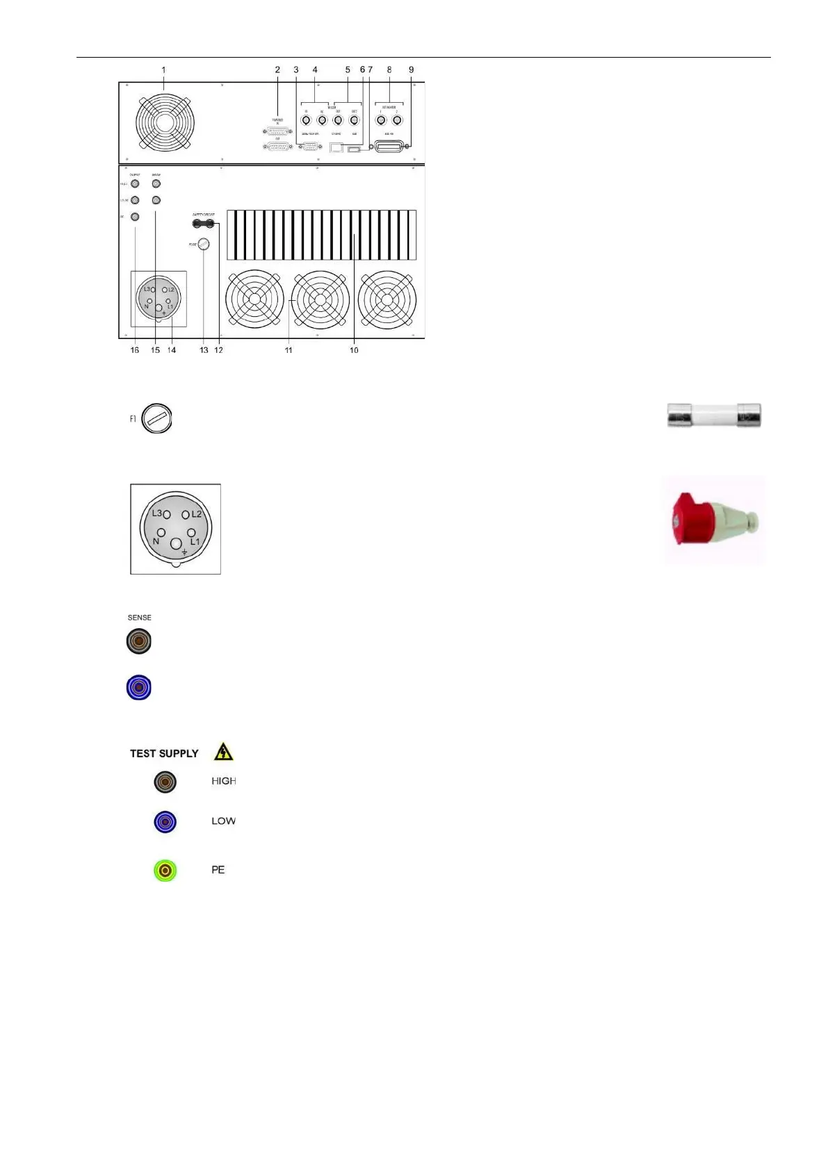
1 Ventilator controller part
2 Framebus IN / OUT
3 Serial from DPA 500N / 503
4 Trigger IN1 / IN2
5 Trigger OUT1 / OUT2
6 Ethernet port
7 USB port
8 DUT monitor
9 GPIB / IEEE 488 port
10 Heat Sink air output
11 Ventilator ( output)
12 Safety circuit
13 Fuse 3.15 A slow blow ( ctrl)
14 Mains in CEE 32 A 3x400 V
15 Sense input
16 Test supply output
Fuse for control unit
Fuse type : 3.15 A slow blow
Dimension : 5 x 20 mm
14. Mains input CEE 32 A connector
Power input connector
CEE Type 32 A
5 pole 3 x 400 V
The sense is switchable to internal or external
The sense plugs are located at the rear of the unit. The external sense
inputs allow the power system output voltages to be monitored directly at
the load and must be connected to the load when the sense is
programmed for external.
The NetWave offers two output plugs for the test voltage. One test
supply output is located at the front and one at the rear of the unit. The
test supply outputs are connected in parallel.
Connector AC Mode DC Mode
HIGH (L) Phase positive
LOW (N) Neutral negative
PE PE PE
 Loading...