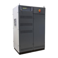
1 Signal out (control)
2 Source in (control)
3 Trigger IN1/2
4 Trigger OUT 1/2
5 GPIB / IEEE 488 port
6 USB for data storage
7 Ethernet port
8 Serial from DPA 503
9 Framebus OUT
10 DUT monitor
11 USB 2 option measuring board
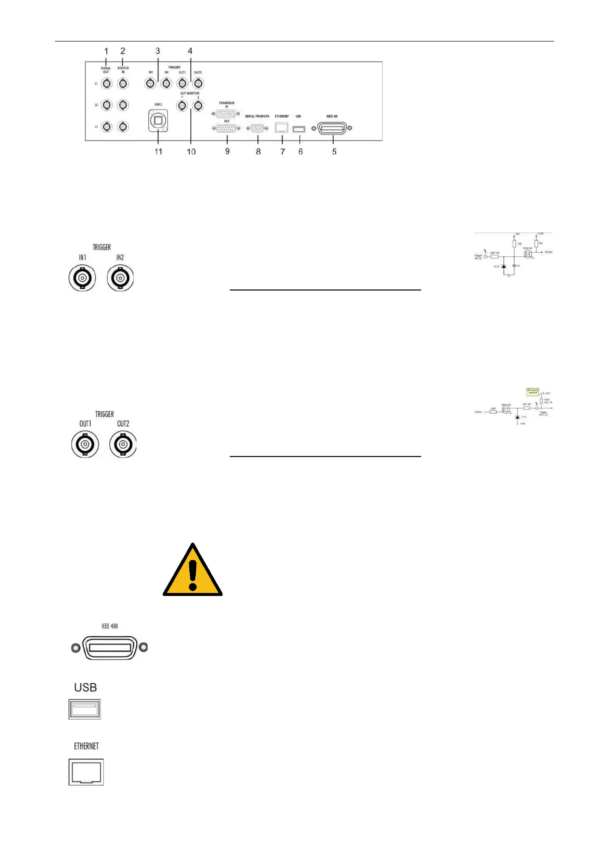
3 Trigger IN
More information sees rear side 1-phase NetWave in the previous chapter
Trigger input for event triggering. This trigger inputs
are connected directly to the DSP signal processor.
Input Signal : Negative slope
Input Function Remarks
Trigger IN 1 : Wave start
Trigger IN 2 : Wave stop
Trigger IN 2 : Sync. Input (for Source AC
Mode, only for NetWave 7.3,
20.x, 30.x, 60.x, 90.x
refer to Annex 9.2)
Trigger output for event triggering. This trigger
outputs are generated from the DSP processor.
Max. voltage: 24V ( pull up )
Current : 100mA
Output Function Remarks
Trigger OUT 1&2: at Start / Stop / Cycle / Break /
Iteration
Trigger OUT 2 :Trigger Channel (Arbitrary Trigger
in Point Power AC and Simple AC
Mode, only for NetWave 7.3, 20,
20.2, 30, 30.2, 60, 60.2, 90.2)
NOTE : For use the trigger out the user must connect
an external DC source for pull up the trigger
signal. . If no external dc source is available,
a T-connection to Trigger IN will deliver the
dc signal.
Parallel interface GPIB / IEEE 488, IEEE 488
interface with IEEE connector.
USB port for data storage tests from/ to a memory
stick.
The network controller supports a 10 / 100Base-
Tinterface. The device auto-negotiates the use of a
10Mbit/sec or 100Mbit/sec connection.
Pin assignment
1: TXD+
2: TXD
3: RXD+
4: RXD-
 Loading...