AMETEK CTs NetWave
Interlock
Two versions of the Interlock exist, depending on the model.
Note for .5 models:
the interlock CONTROL must be closed to enable the output. Use either
the delivered INTERLOCK Terminator or other external switch.
See chapter 10.2 for further explanations.
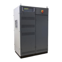
Switch Floating / Grounded
Switch to open/close the Neutral – Ground( PE) connection
Default setting: PE
Floating: Is used when
- the power system reference is floating and the ground
(PE) is not connected to neutral inside the NetWave
- PE is connected to any line
- the test requirement defines another PE reference
Max voltage between: Line to PE and Neutral to PE
For all models except xx.5:
V ac (rms) Vdc
Line to PE: 430 V 600 V
Neutral to PE: 360 V 500 V
Note: in High Voltage DC Mode (Opt-3 DC-EVR) the voltage is limited to
600VDC when the switch is set to “floating”. This prevents the damage of
the internal voltage limiters to be overloaded in case of a wrong
connection.
Note: see chapter 9.10 for special conditions when the optional
insulation monitoring device (Opt-3 IMD) is installed.
For xx.5 models:
V ac (rms) Vdc
Line to PE: 700 V 1000 V
Neutral to PE: 360 V 500 V
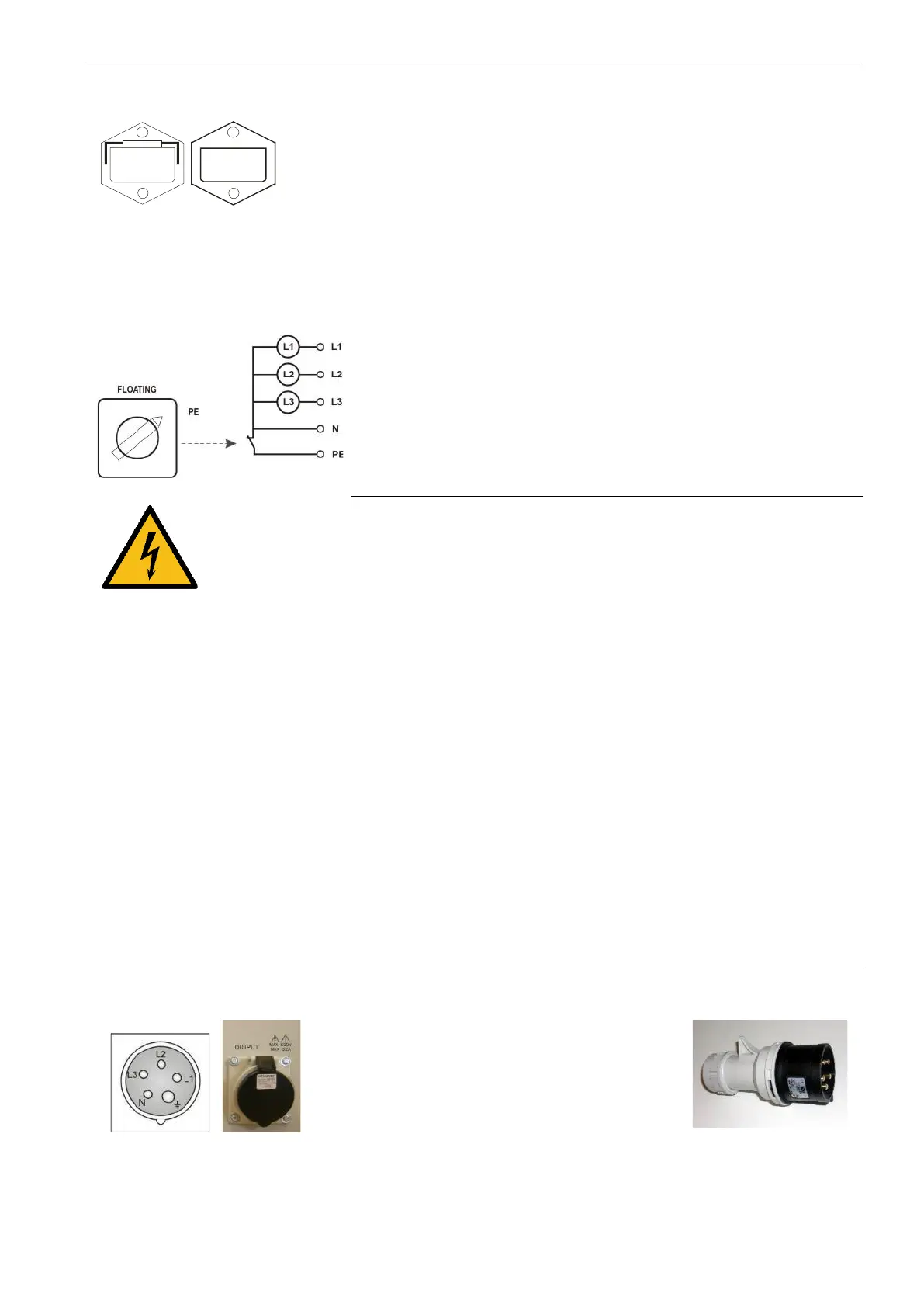
Test supply output terminals
Power Output connector
CEE Type 32 A
5 pole 3 x 690 V
4.3.8. Opt-3 Parallel Mode - NetWave 20.x and 30.x (Option)
The parallel mode will connect all three internal sources together in parallel. The common 1-phase output is on
a terminal block (2) where the user must connect the EUT. The other EUT terminals for 3-phase operating are
disconnected from the source.
- All 3 sources are connected in parallel
 Loading...