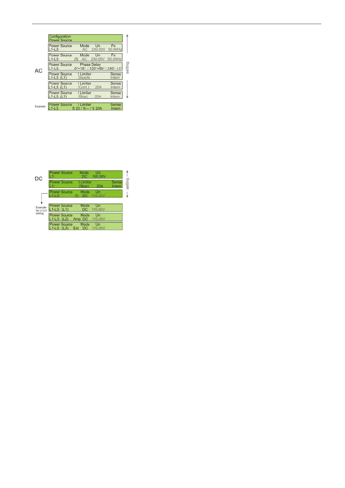
L1 Selected output channel for setting the parameters.
Cyclic settings for L1 to L3 if available
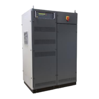
Mode AC or DC
Un Output Voltage : AC rms / DC
Fn Frequency : AC only
(!) The 3-phases are not identical (internal and/or external)
Limiter Settings for the current limiter function (see below)
1
st
set : RMS or Peak
2
nd
set : Disable, Stop, Continuous
I Limiter Current value : 2...100A dep. on model, mode, frequency
Sense Sense input : internal / external and compensation (see
below)
The example shows the settings:
L1 Stop 20A,
L2 disabled
L3 Stop 20A
This example shows:
L1: Is set to internal source
L2: Use a looped AMP
L3: Use an external DC source controlled by L3
Current limiter function
RMS the current limiter is based on and limits the RMS value of the output current. When the output
current reaches the set limit, the rms current is reduced to stay within the set limit (Continuous
mode) or stops (STOP mode). The output voltage is not distorted.
The mode works best for passive loads but can be instable in case of active loads (i.e. batteries
or converters)
Peak the current limiter is based on and limits the peak current. When the peak current reaches the
set limit, the peak current is clipped (continuous mode) or stopped (STOP mode). This might
lead to a distorted voltage signal.
This mode is best for active loads (i.e. batteries or chargers) or if the load draws high peak
currents
STOP The power is switched off when the current reaches the programmed value
Continuous Reduces the voltage in case of tripping until the programmed current is reached
Disable No current limit. Allows the max. inrush current for 3 to 6 seconds and switch the power off if it
does not reduce
Depends on the source model; indicates the numbers of phases.
L1 for single phase equipment (L1, N, PE)
L1 + L2 180º phase shift split power (L1, L2, N, PE)
L1 – L3 for 3-phase equipment (L1, L2, L3, N, PE)
The current limiter function works also for reverse currents (power sink mode).
 Loading...