AMETEK CTs NetWave
The following steps are required to setup NetWave Cascade Source :
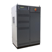
- The NetWave Master (L,+) is setup in the menu “Standalone/Master/Slave” to the mode “Master (L1, L,+). The
Source is set to function “CascadeSource”.
The NetWave works as a Master in parallel
mode and is phase L or +. The controller
controls the connected Slave NetWave.
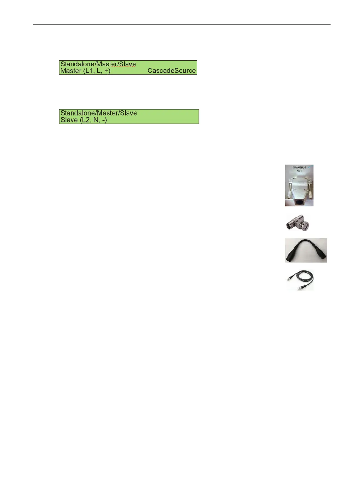
- The NetWave Slave (N,-) is setup in the menu “Standalone/Master/Slave” to the mode “Slave (L2, N,
-)”.
The NetWave works as a Slave in parallel
mode and is phase N or -. The controller is
inactive. The NetWave hardware is
controlled by the NetWave Master.
- The Framebus OUT of the NetWave Master (L,+) is connected to the Framebus IN of the NetWave
Slave (N,-)
- The Framebus IN of the NetWave Slave (N,-) muss be terminated with
a Framebus Terminator.
- At the Signal OUT1 of the NetWave Master (L,+) a BNC T-Adapter
is connected.
- The Signal OUT1 (BNC T-Adapter) of the NetWave Master (L,+)
is connected to the Signal IN1of the NetWave Master (L,+)
- The Signal OUT1 (BNC T-Adapter) of the NetWave Master (L,+)
is connected to the Signal IN2 of the NetWave Slave (N,-).
- Each NetWave is supplied.
- Switch the PE at NetWave Master (L,+) to ground.
- Switch the PE at NetWave Slave (N, -) to floating.
- The PC computer is only connected to the NetWave Master (L,+).
- The EUT is connected to each NetWave.
The N from each NetWave are not connected.
The PE from each NetWave are not connected.
 Loading...