Installation Guide | 3-15
Combustibles RCU
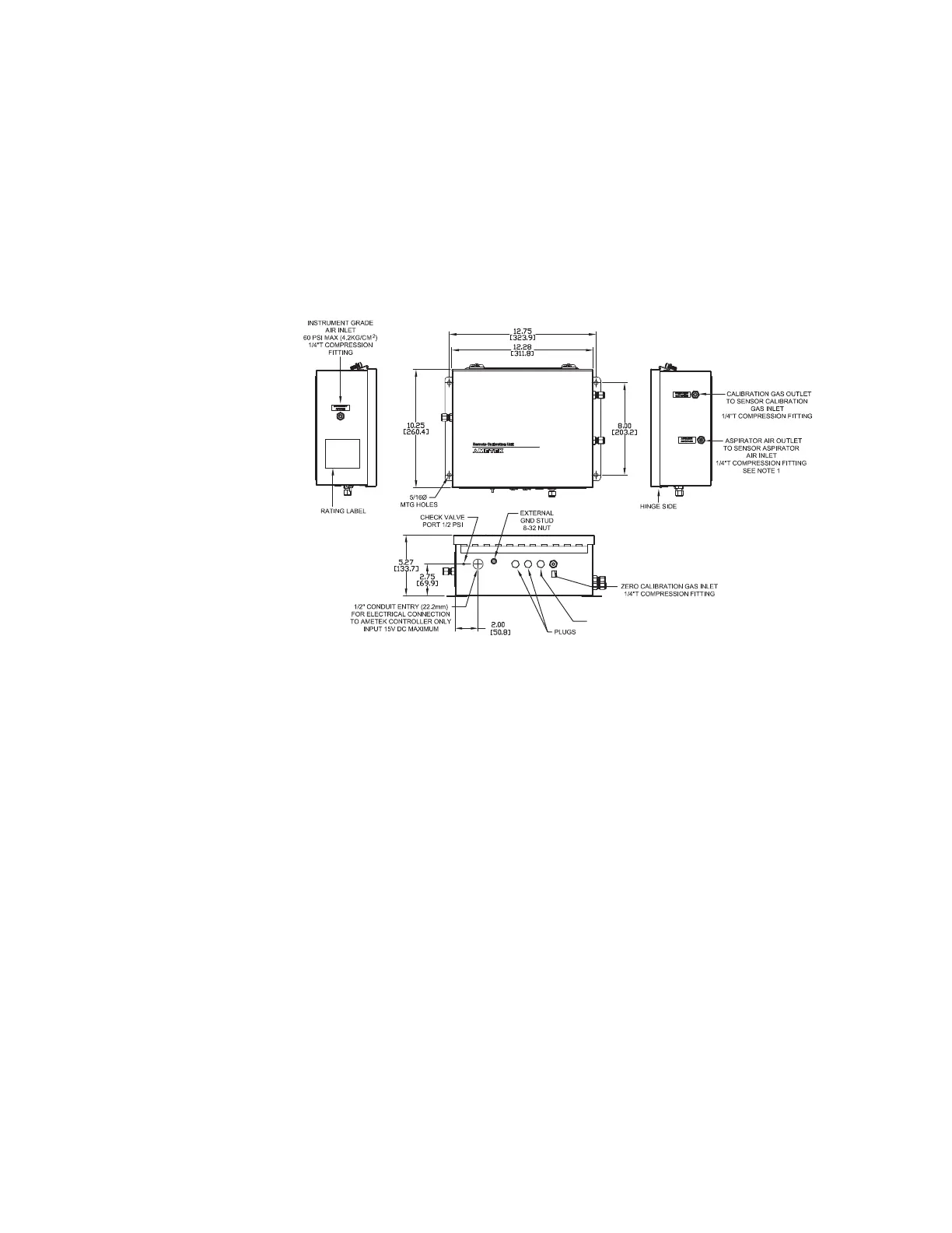
Figure 3-15 shows mounting dimensions for the combustibles RCU. Mount the
RCU as close to the sensor as possible. Shorter calibration plumbing improves
response times, reduces calibration gas expense, and reduces the chance of con-
taminants in the calibration gas plumbing. The ambient temperature range for the
combustibles RCU is -20° to 70°C.
Make the following calibration gas connections to the combustibles RCU.
COMBUSTIBLES (SPAN 2)
CALIBRATION GAS INLET
1/4” COMPRESSION FITTING
Figure 3-15. RCU mounting dimensions - Combustibles.
1. Connect the O
2
span gas, if other than instrument air, to the alternate
O
2
span gas inlet.
2. Connect the O
2
zero calibration gas to the O
2
zero gas inlet connection
on the RCU.
3. Connect the combustibles span calibration gas to the combustibles
span gas inlet on the RCU. For a WDG-VCM analyzer with RTD-type
combustibles detector, the combustibles span calibration gas would
also include the methane span calibration concentration.
4. Using appropriate tubing, connect the calibration gas outlet on the
right side of the RCU to the calibration gas inlet on the sensor - see
Figure 3-13 for sensor calibration gas inlet connection.
5. Using appropriate tubing, connect the aspirator air outlet on the right
side of the RCU to the aspirator air inlet connection on the sensor.

 Loading...


