3-22 | Thermox WDG-V / VC / VCM with Blow Back
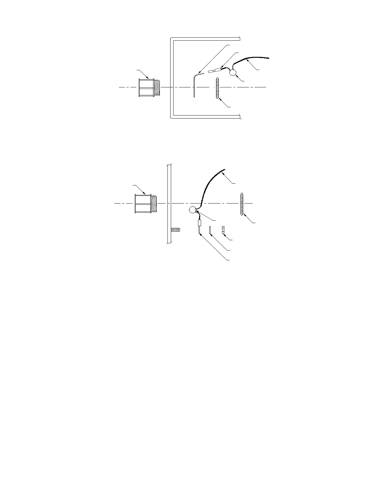
SHIELD RING METHOD
GROUND STUD METHOD
Shield Terminal Ring
Conduit Housing
Cable Shield(s)
Max. Length 1 inch
Conduit Nut
Quick Disconnect (1/4”)
Capacitor
Conduit Nut
Cable Shield(s)
Max. Length 2 inches
Nut
Washer
Ring Terminal
Conduit Housing
Capacitor
Figure 3-19. Direct shield grounding methods
Transient and RFI Interference
This section describes transient and RFI interference precautions:
• Although there are transient and noise protectors on all sensor unit
I/O connections (communications, current outputs, sensor, etc.), this
protection is intended to act as a last line of defense against unwanted
transient and RFI interference.
• Proper installation practices to prevent the introduction of transients
and noise into the system must be followed. Inductive loads connect-
ed to the sensor unit must have transient suppressors installed at the
inductive loads. Be sure to place the transient suppressor as close to
the load as possible. Examples of transient suppressors include MOVs,
TRANSORBs, and RC snubbers.

 Loading...


