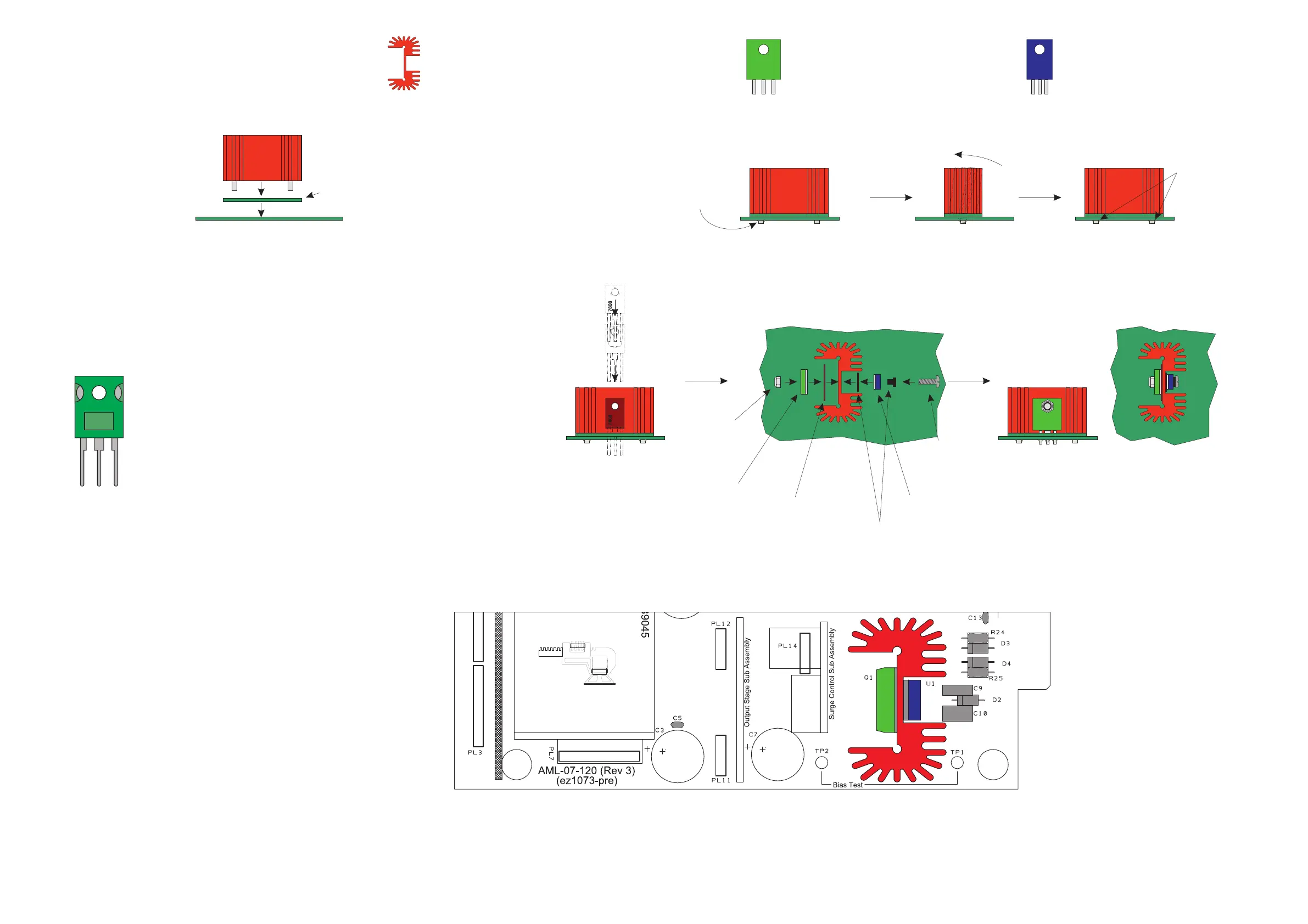
Transistor and Regulator
HS1 = Heatsink
+ heathink insulator PCB
Q1 = TIP3055 Transistor (1)
Tack in place first then check
they are vertical before
soldering completely.
Check Vertical
Tack in place.
2 43
Solder fully
Install the TIP3055 on the left side of the
heatsink in position Q1, and the 7808
on the right side of the heatsink in position U1,
(with their rear sides towards the heatsink)
with a TO247 insulator behind the TIP3055
device and a TO220 insulator behind and a
bush in front of the 7808. Secure in place with
an M3 x 12mm screw and Nyloc nut.
Trim legs and then solder in place.
The TO220 insulator may be trimmed to fit
better.
4
5
6
TIP3055
Insert heatsink through
insulator PCB
then into main PCB
1
Heatsink Insulator
PCB
Front
View
TIP3055
U1 = MC7808 Regulator (1)
MC8708
+ TO247 insulator
(bush not required)
+ TO220 insulator
(with bush)
M3
Nyloc.
TIP3055
TO220
Insulator
+ Bush
M3 x 12mm
MC7808
TO247
Insulator