Output Transformer Assembly and Fitting
T2 = VTB2569 (1)
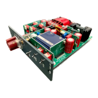
Plug the output transformer molex connector into molex on the PCB
MAKE SURE THAT THE CONNECTOR IS FITTED SO THAT THE
WIRE COLOURS ARE AS SHOWN BELOW.
[This may require the cable to be rotated round].
Assembly Tip:
It is usually easier to plug in
the molex connector before
screwing the transformer in
place
VERY IMPORTANT:
Do NOT tighten the screws very tight...
use a thread locking adhesive applied to
the end of the screw.
Overtightening will alter the air gap... that would
not be good !
Brown
Violet
Red
Green
Blue
Orange
Black
Yellow
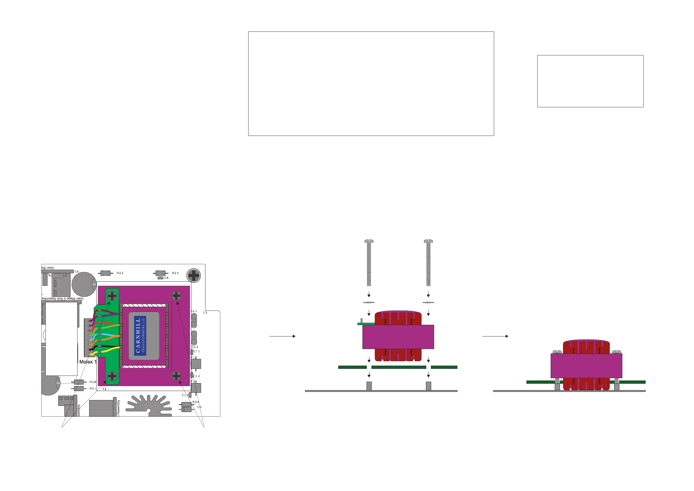
M3 x 30mm screw
at front 2 holes
M3 x 28mm screw
at rear 2 holes
Brown
Violet
Red
Blue
Green
Orange
Black
Yellow
AML-07-128 (rev 2)
Gently screw the output transformer to the chassis using 2 x M3 x 28mm screws
and 2 x M3 x 30mm screws and 4 x M3 shakeproof washers. Do not overtighten the screws.
Ideally, apply some LocTite thread adhesive to the screws (if available).
M3 x 28mm screw
at rear 2 holes
M3 shakeproof washer
M3 x 30mm screw
at front 2 holes