AMSAFE SEATBELT AIRBAG SYSTEM
INSTALLATION, HANDLING AND SHIPPING INSTRUCTIONS E510629
REMOVAL REPLACEMENT AND INSTALLATION PROCEDURES
02-Aug-2013
Page 3004
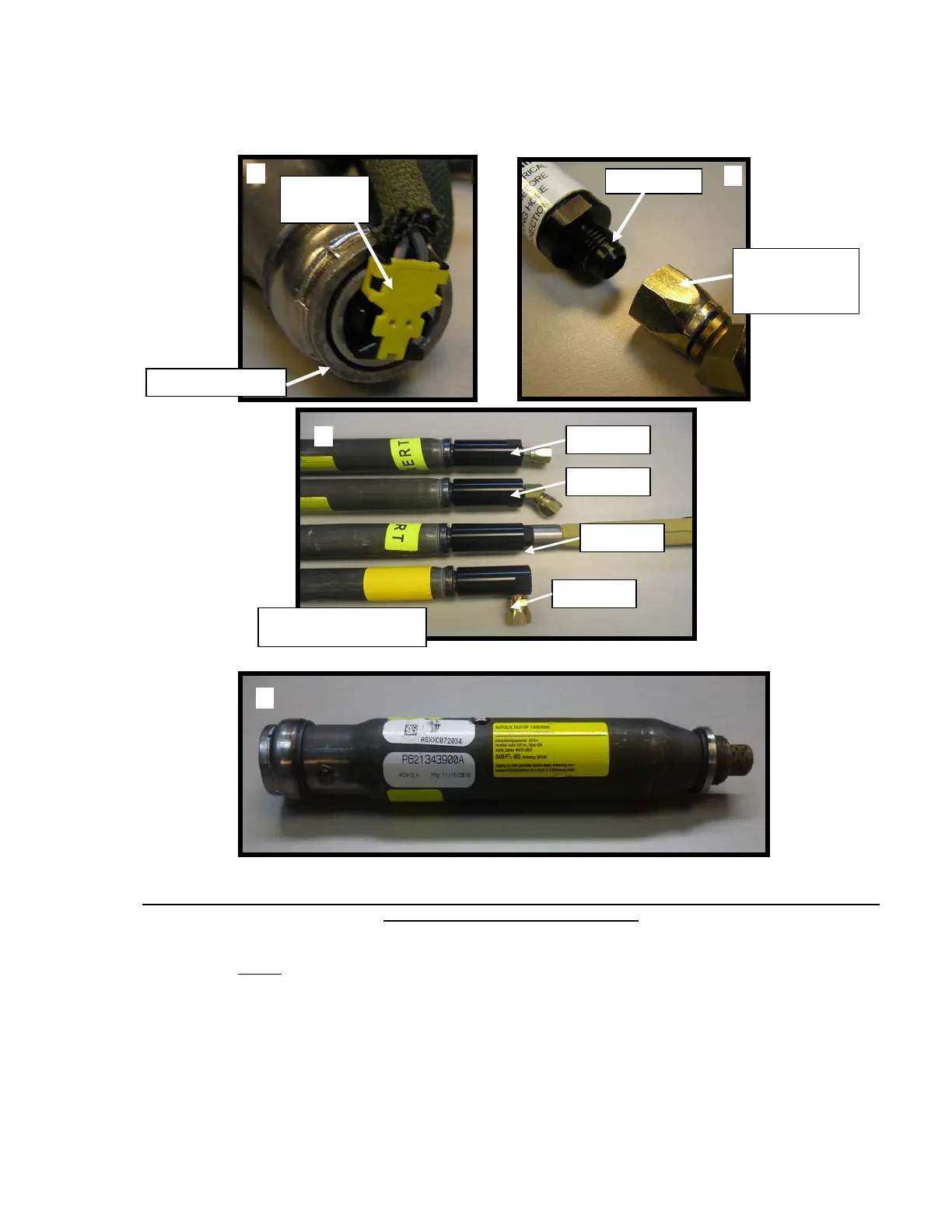
Figure 11: Electrical Connection to Inflator, Hose Connector to Inflator Fitting, Inflator Fittings to Inflators, ACH
2.4 Inflator (no inflator fitting required)
NOTE
: THE ACH 2.4 INFLATOR (FIGURE 11D) DOES NOT REQUIRE AN INFLATOR
FITTING. THE HOSE CONNECTION SHOWN IN FIGURE 11B IS MADE
DIRECTLY TO THE INFLATOR WHEN USING 2.4 INFLATOR.
(3) Remove the Inflator from its mounting hardware (refer to seat OEM installation drawing for
specifics on attaching hardware for Inflator).
(4) Disconnect the gas hose from the Inflator or Inflator Fitting depending on what type of inflator
is being used (Figure 11B). If the inflator has an Inflator Fitting, disconnect it from the Inflator
(Figure 11C). The gas hose barb and the Inflator threads are Loctite 242 coated, which
B
Inflator Fitting
Hose
Connection
C
Inflator Fitting to Inflator
Connection Point
90-degree
0-degree
0-degree
45-degree
D
A
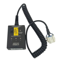
Squib
Connector
Inflator Front End