Appendix A – Adding or Replacing Boards
237
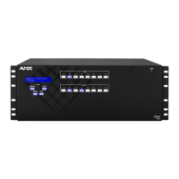
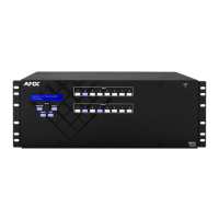
Hardware Reference Manual – Enova DGX 100 Series Digital Media Switchers
CAUTION: Each Enova DGX board has an EMI gasket along one edge of the faceplate. Handle the boards carefully to avoid
dislodging or damaging the gasket on the board being installed
and the gasket on the adjacent board or blank plate.
CAUTION: For DXLink Fiber Boards, do not remove dust plugs from their fiber connectors until Step 12.
5. Audio Switching Boards (ASB and ASB-DAN) only –
Do not install in enclosure with AIE boards.
Must be installed in pairs.
Must be installed in expansion slots.
Enova DGX 6400 only – Be sure to install all four boards in correct expansion slots (see page 143).
For Enova DGX 800/1600/3200 systems only – Attach HSSI cable from SMA port on ASB Input Board to SMA port on ASB
Output Board.
6. Audio Insert/Extract Boards only – See page 158 for information on setting the DIP switches (this is the only way to
configure the insert/extract functionality). Flip the DIP switch for each connector that needs its setting changed. We
recommend writing down the setting for each connector to make verifying correct audio switching behavior easier in Step 14.
AIE Boards can only be installed in an expansion slot (FIG. 118 and FIG. 119).
IMPORTANT: Unused AIE connectors must be set to “Disable/Extract.”
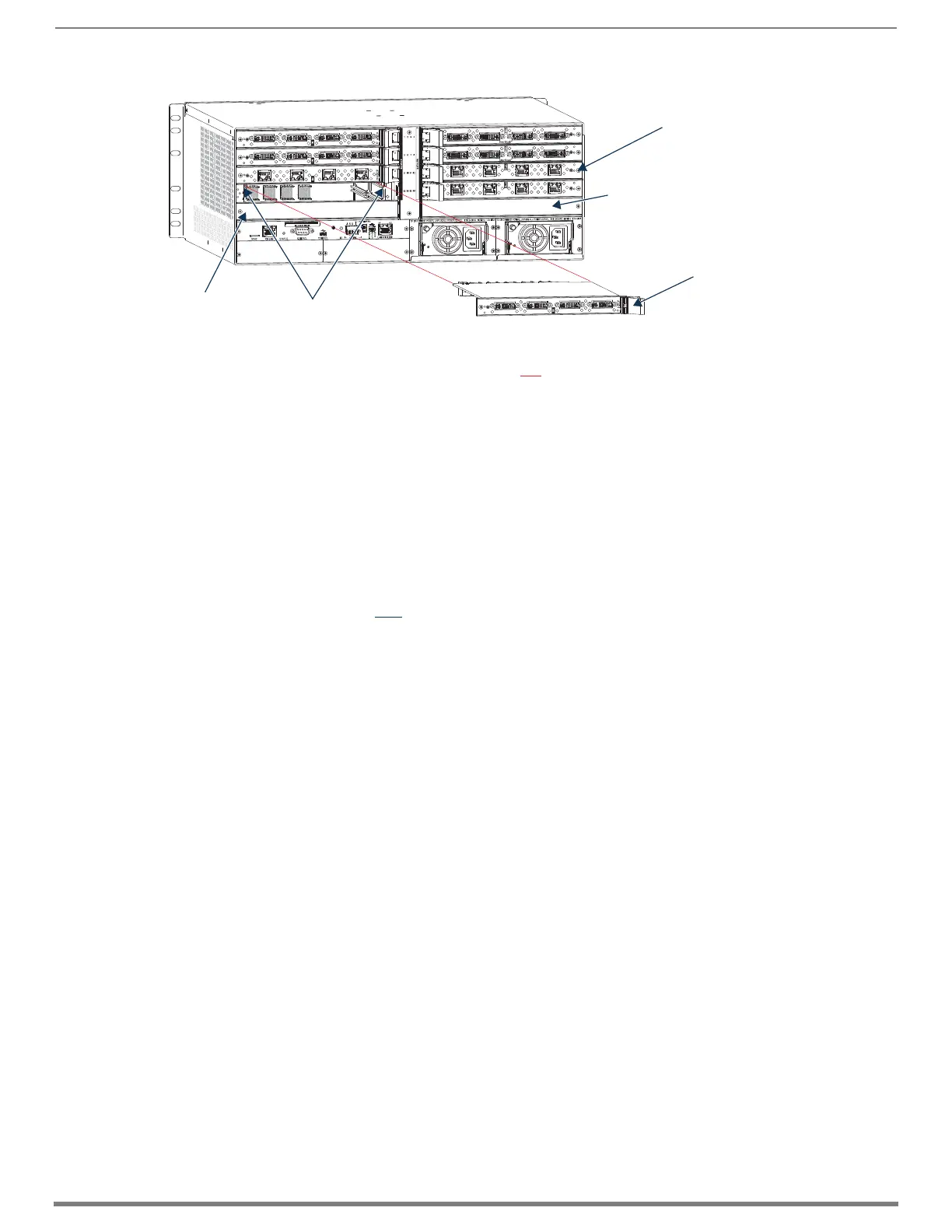
7. Install vertical boards – With the board’s extractor handle in the extended (unlocked) position, line up the board’s edges on
the board guides that are along the top and bottom of the board slot (FIG. 118).
Or
Install horizontal boards – With the board’s extractor handle in the extended (unlocked) position, line up the board’s edges
on the board guides that are along the left and right of the board slot (FIG. 119). Note that input boards have board guides at
the top of the slot and board guides for the output boards are at the bottom of the slot due to their reversed orientation in the
enclosure.
8. Begin pushing the board into the slot until the extractor handle starts to engage the metal extractor plate (the extractor
handle moves into its folded position).
When the extractor handle starts to lift, flip the handle toward the center of the board until it snaps into its folded (locked)
position, which firmly seats the board.
9. Fasten the screw (which was removed in Step 4) that holds the board in place. This screw must be tightened securely before
cables are attached in Step 12.
10. If the enclosure was powered down – Plug the AC power cords back into the power supplies.
11. Verify that the system recognizes the board:
a. Launch the System Configuration interface
b. Navigate to the Switcher/Status page.
c. Scroll down to the Input or Output Board slot number of the new board.
(Audio boards will be listed under “expansion boards.”)
d. Ensure that the board’s Status is “OK” and that the Type field is correct.
e. If the fields do not reflect the board you have inserted, or the board Status states “FAIL,” re-seat the board and check the
Status page again.
f. If the firmware version on a board does not match the enclosure (indicated with an asterisk in the Version column),
download the latest .kit file and send it to the enclosure (instructions on page 180).
NOTE: If using a cable management bar, tie the cable to the cable management bar far enough below the connector to allow for the
manufacturer’s recommended bend radius.
12. Attach cables to the board’s connectors* and reconnect any other cables that were disconnected in Step 3
(if applicable – tie cables to cable management bars). If the enclosure was powered down – Reapply power.
13. Optional – If you have custom board settings to load to the board, use the System Configuration interface to load them now
(see page 169).
FIG. 119
Horizontal boards - Remove screw, push extractor handle right (input) or left (output), pull board straight out
AC
DC
FLT
AC
DC
FLT
One screw holds each
board or board plate in
place
Push board extractor
handle toward center
of enclosure into
extended position
Expansion slot
Board guides
Expansion slot
 Loading...