Appendix E – Upgrading/Downgrading the System
261
Hardware Reference Manual – Enova DGX 100 Series Digital Media Switchers
Items Required
□ Enova DGX 100 Series replacement CPU board
□ Phillips #1 screwdriver
□ ESD wristband and cord with an alligator clip
ESD WARNING: To avoid ESD (Electrostatic Discharge) damage to sensitive components, make sure you are properly grounded
before touching any internal Enova DGX materials. Use an ESD wristband and cord with an alligator clip attached to a good
ground source.
To remove and replace an Enova DGX CPU board assembly:
NOTE: If SC Fiber Boards are in the enclosure, remove them before beginning the following instructions.
1. Turn off AC power to the enclosure. Make sure none of the power supply LEDs are illuminated.
2. Disconnect all cables connected to the CPU and power supplies.
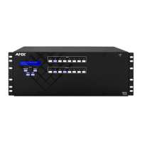
3. Remove the screws from CPU faceplate per the locations indicated in FIG. 132 (seventeen screws in Enova DGX 64, three
screws in Enova DGX 8/16/32).
4. Remove the CPU faceplate and set aside.
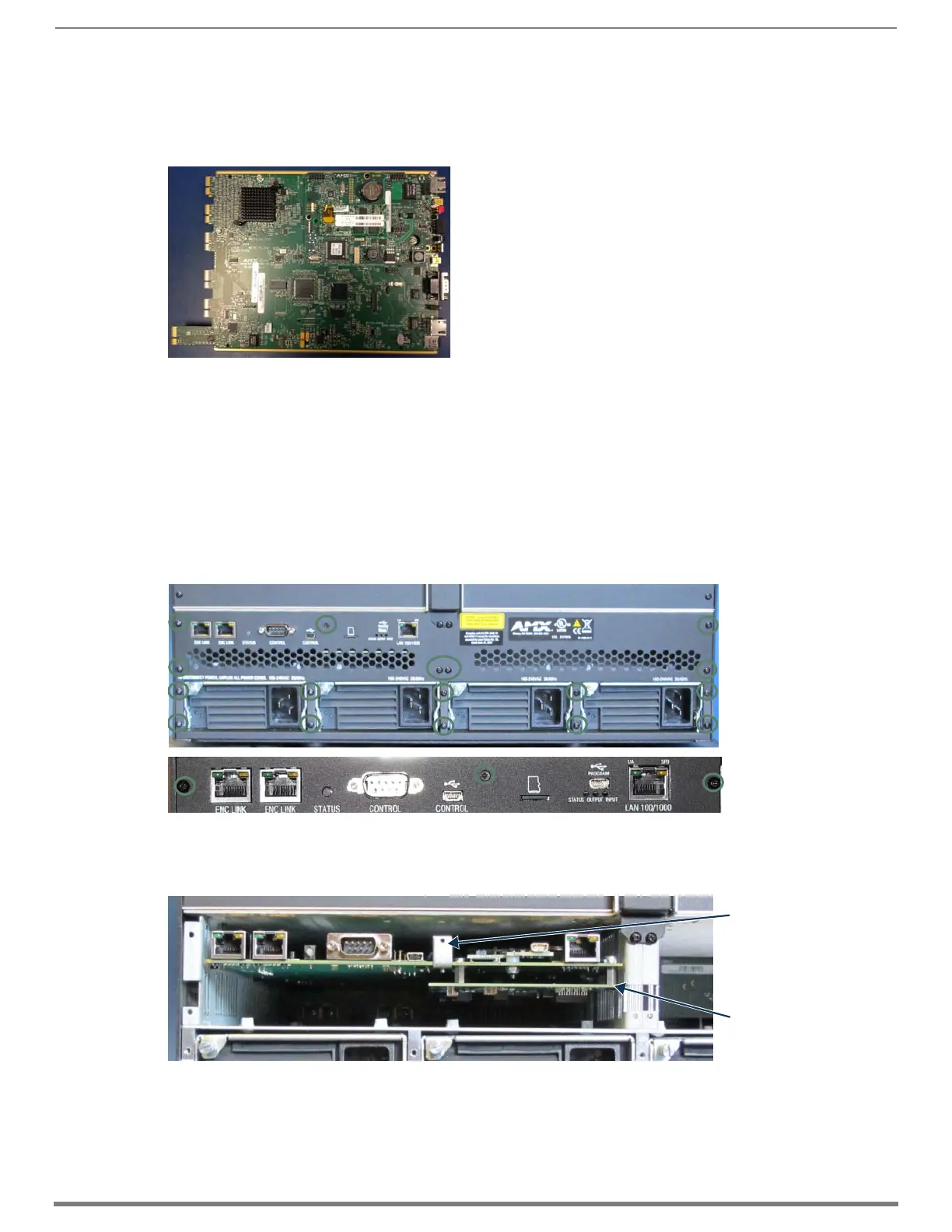
5. Use the removal tab indicated in FIG. 133 to pull the CPU board assembly straight out of the enclosure.
6. Place the old CPU board in an ESD approved static shield bag and set aside.
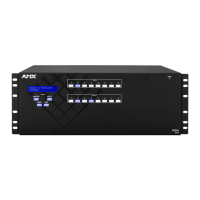
FIG. 131 Enova DGX 100 Series CPU board (top view)
FIG. 132 Remove screws that hold faceplate
FIG. 133 Use removal tab to pull CPU straight out
Enova DGX 64
Enova DGX 8/16/32
NOTE: The only CPU with
a bottom daughter board
is the Enova DGX 64.
Removal tab
 Loading...