Installation and Setup
46
Hardware Reference Manual – Enova DGX 100 Series Digital Media Switchers
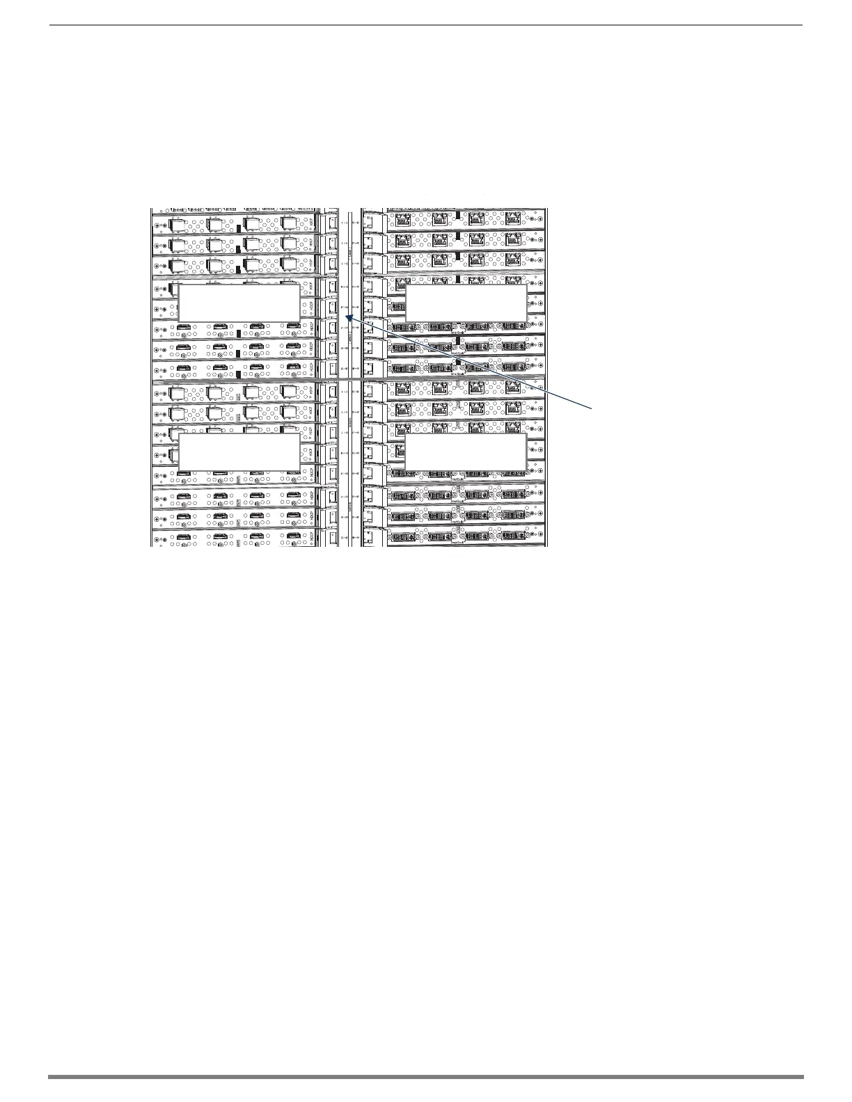
Enova DGX 6400
The Enova DGX 6400 has input boards at the top of the enclosure’s rear and output boards below.
Enclosures have 32 horizontal board slots (16 slots each for the input and the output boards, with 4 connectors per board),
allowing for a maximum configuration of 64x64 (FIG. 22).
Input and output channel numbers correspond to the connectors and are located in the middle of the enclosure between
boards on either side. For inputs, numbering is consecutive from left to right on each board from the top input board on the
left to the bottom input board on the left, continuing on the top input board on the right to the bottom input board on the
right. Outputs start over at “1” and follow the same pattern.
Cabling Specific Connector Types
For information on board connectors and cabling and specifications for specific types of connectors:
HDMI Boards – page 70
DVI Boards – page 79
DXLink Twisted Pair Boards – page 91
DXLink Twisted Pair 4K Boards – page 97
DXLink Fiber Boards – page 118
Input and Output Signal Cables
CAUTION: If you are connecting switching systems via their DXLink ports (applies to DXLink Twisted Pair 4K Boards, DXLink Twisted
Pair Boards, and DXLink Fiber Boards), be sure to read the information on page 97 (DXLink Twisted Pair 4K), on page 90 (DXLink
Twisted Pair), and on page 117 (DXLink Fiber).
If using cable management bars, install them before attaching the cables (see page 44).
Before connecting all of the input and output cables and wires, attach only the ones for the first two sources and destinations (and
any applicable transmitters and receivers). Complete the remaining installation tasks (applying power and any system setup
though the System Configuration interface), and then disconnect the factory default switch and execute a test switch (see
page 56). When the test switch is successful, attach the remaining input and output cables and wires.
FIG. 22
Numbers on numbering plate indicate input and output board channels
Output connectors
Numbering plate
Input connectors
Output connectors
Input connectors
 Loading...