UG-1134 EVAL-ADAU1467Z
Rev. A (Draft) | Page 12 of 55
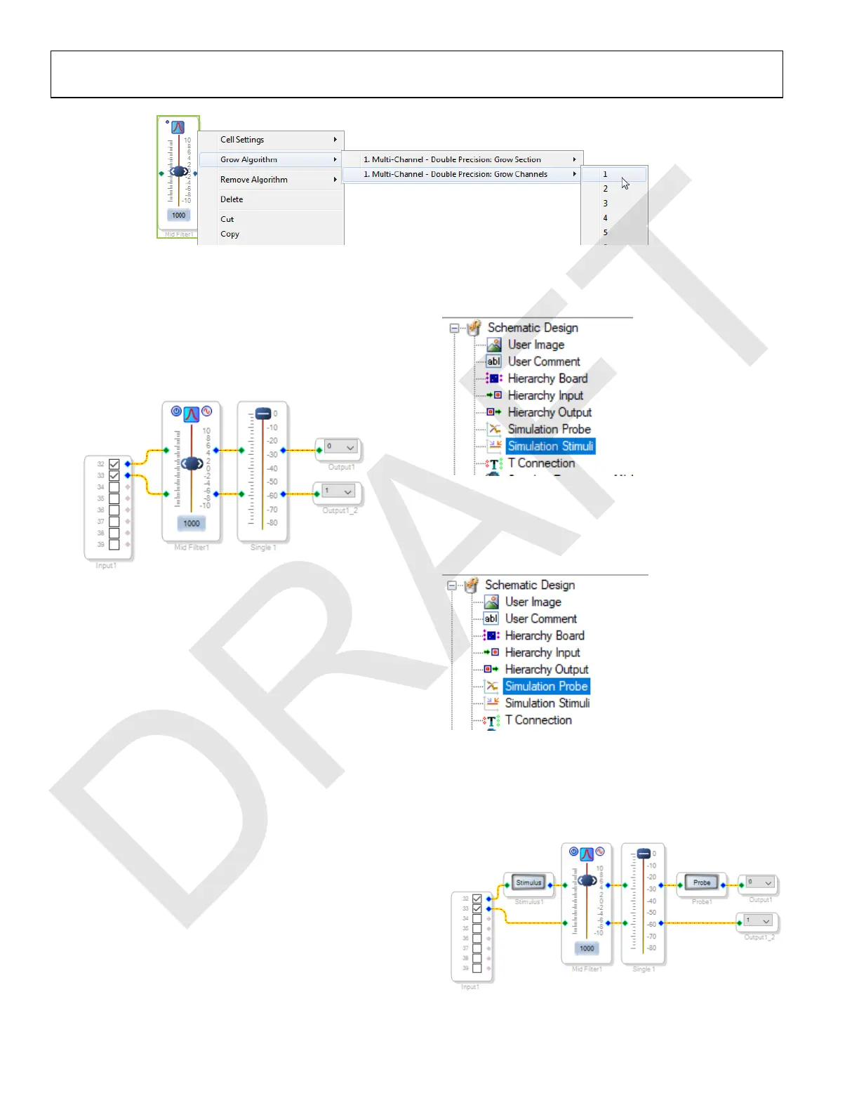
Figure 29. Adding a Channel to the Filter
2. Connect the filter in series between the Input block and
the Single Volume blocks so that the filter can be applied to
the signals passing through the DSP. The completed signal
flow resembles Figure 30.
Figure 30. Completed Signal Flow with Filter
3. Click the Link/Compile/Download button (see Figure 24)
or press F7 to compile the signal flow and download it to
the hardware. The audio signal passes from input through
the volume control and the EQ filter, and then to the
output. To change the settings of the EQ filter, click the
blue icon at top of the block. To change the filter gain in
real time while the project is running, drag the control
slider in SigmaStudio.
The Simulation Stimulus and Simulation Probe blocks may be
used to visualize the magnitude and phase response of a linear
chain of blocks. The response is calculated on the host PC and
is a simulation using the same filters that are running on the
ADAU1467.
To visualize the filter response, take the following steps:
1. From Schematic Design at the top of the ToolBox window,
add a Simulation Stimuli block to the project space as (see
Figure 31. Simulation Stimuli Block).
Figure 31. Simulation Stimuli Block
2. From Schematic Design at the top of the ToolBox window,
add a Simulation Probe block to the project space as (see
Figure 32. Simulation Probe Block).
Figure 32. Simulation Probe Block
3. From Schematic Design at the top of the ToolBox window,
add a Simulation Probe block to the project space as (see
Figure 33. Signal Flow with Simulation Stimulus and
Probe).
Figure 33. Signal Flow with Simulation Stimulus and Probe

 Loading...

