EVAL-ADAU1467Z UG-1134
Rev. A (Draft) | Page 25 of 55
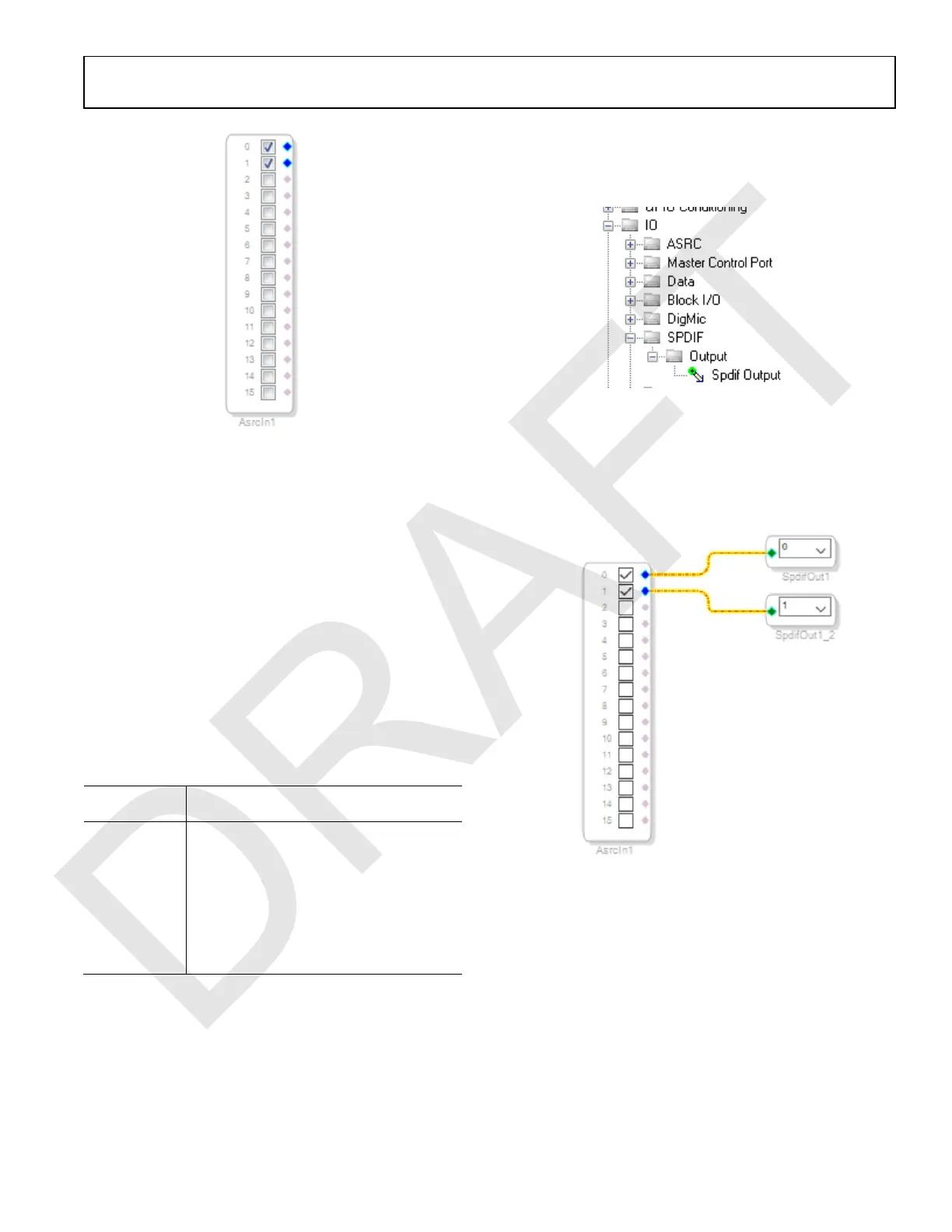
Figure 73. ASRC Input Block
Because the left and right signals of the S/PDIF receiver are
passing through the ASRC 0, the input to the DSP program is
the Asrc Input block in SigmaStudio. This naming convention
is such that all blocks in SigmaStudio are named from the
perspective of the DSP core. Therefore, the Asrc Input block
in SigmaStudio represents the input to the DSP from the
ASRC outputs. The inputs to the ASRCs themselves are
defined in the register window (see Figure 68).
By default, Channel 0 and Channel 1 are active when their
corresponding checkboxes are selected. Because the ASRC 0
outputs correspond to Channel 0 and Channel 1, this default
configuration can be used (see Figure 73). For reference, a
mapping of the ASRC outputs to the corresponding channels
on the Asrc Input block in the DSP schematic is provided in
Table 4.
Table 4. ASRC Output to SigmaStudio Input Channel Mapping
Corresponding Channels on ASRC Input
Block in SigmaStudio
ASRC 0 Channel 0 and Channel 1
ASRC 1 Channel 2 and Channel 3
ASRC 2 Channel 4 and Channel 5
ASRC 3 Channel 6 and Channel 7
ASRC 4 Channel 8 and Channel 9
ASRC 5 Channel 10 and Channel 11
ASRC 6 Channel 12 and Channel 13
ASRC 7 Channel 14 and Channel 15
8. Add two S/PDIF outputs to the project as follows:
b. From the IO > SPDIF > Output folder, click Spdif
Output (see Figure 74) and drag it into the project
space to the right of the toolbox.
Figure 74. S/PDIF Output Block Selection
c. Repeat the previous step to add another Spdif
Output block.
9. Connect the signals from the Asrc Input block to the Spdif
Output blocks so that the resulting signal flow resembles
Figure 75.
Figure 75. Signal Flow Including S/PDIF Input (via the ASRC)
and S/PDIF Output
10. Click the Link/Compile/Download button (see Figure 24) or
press F7. The signal flow then compiles and downloads to
the hardware.
11. Confirm proper operation by checking that any signal
input to the S/PDIF optical receiver is copied and output
on the S/PDIF optical transmitter.
 Loading...


