UG-1134 EVAL-ADAU1467Z
Rev. A (Draft) | Page 24 of 55
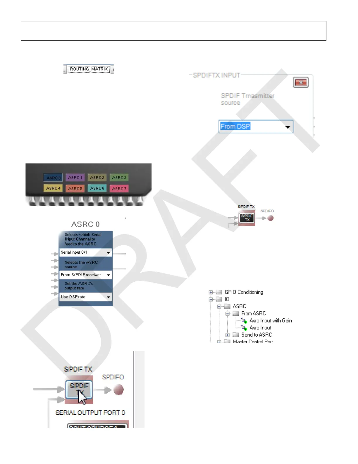
3. Click the ROUTING_MATRIX tab (see Figure 66) to
allow the configuration of the routing matrix.
Figure 66. Selecting the ROUTING_MATRIX Tab
4. To configure the S/PDIF receiver signal routing, click the
first asynchronous sample rate converter, ASRC 0 (see
Figure 67) and configure ASRC 0 using the dropdown menus
until it matches what is shown in Figure 68. This
configuration routes the S/PDIF receiver signal through an
ASRC before it is accessed in the DSP core. Routing the
signal in this way is necessary because the clock recovered
from the S/PDIF source is not synchronous to the
ADAU1467.
Figure 67. ASRC 0 Control Button
Figure 68. Configuring the ASRC 0 Routing Matrix Registers
5. Configure the S/PDIF transmitter (Tx) signal routing as
follows:
a. Click the S/PDIF TX box (see Figure 69).
Figure 69. Configuring the S/PDIF Transmitter Routing Matrix Register
b. From the dropdown menu that appears, select From
DSP to choose the signal coming from the DSP core
(see Figure 70).
Figure 70. Routing the DSP Core Outputs to the S/PDIF Transmitter
c. Close the dialog box shown in Figure 70.
d. Confirm that the setting has taken effect by verifying that
the color of the S/PDIF TX box has changed from gray
to black (see Figure 71). If the color of the box changes
to black, the DSP core has been routed to the S/PDIF
transmitter; therefore, the output of ASRC 0 can be used
in the DSP program.
Figure 71. Confirming that the DSP Core Outputs are Routed
to the S/PDIF Transmitter
6. Click the Schematic tab at the top of the window to return
to the schematic design view.
7. Add an S/PDIF input to the project as follows:
a. From the IO > ASRC > From ASRC folder, click Asrc
Input (see Figure 72) and drag it into the project space
to the right of the toolbox (see Figure 73).
Figure 72. ASRC Input Block Selection
 Loading...


