11
Test Diodes and Continuity
1. Connect the black test lead to the COM Terminal
and the red lead to the VΩHz Terminal.
2. Push twice to enter the Diode/Continuity Mode.
3. To test continuity, touch the probes to the
desired test points of the circuit. The built-in
beeper will beep when there is a short circuit.
4. To test diodes, connect the red probe to the
anode side and the black probe to the cathode
side of the diode being tested. Then read the
forward bias voltage value on the display. If the
polarity of the test leads is reversed with diode
polarity or the diode is broken, the display
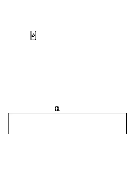
reading shows “ ”.
Measure Capacitance
1. Connect the black test lead to the COM Terminal
and the red lead to the VΩHz Terminal.
*Do not input voltage at this setting.
*Disconnect circuit power and discharge all
capacitors before you test diode.