EasyManua.ls Logo

Anet A8 Plus - Page 33

Anet A8 Plus
49 pages
Print Icon
To Next Page IconTo Next Page
To Previous Page IconTo Previous Page
Loading...
Step 22
No.
Name
Qty.
1
Power outlet
1
2
Red and black with U-shaped line
(Double head)
1
3
M4*6 socket hexagon screw
4
3
T-nut M4
4
4
M3*6 socket hexagon screw
5
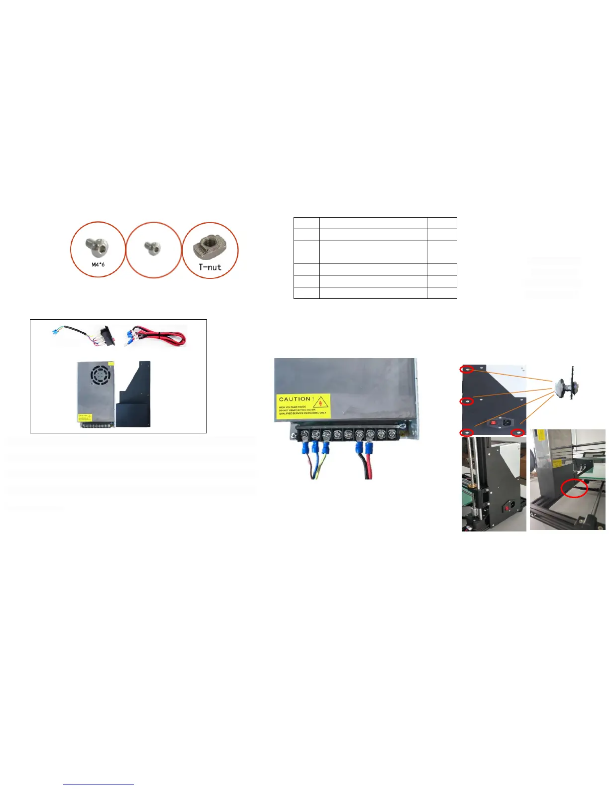
Note: The wiring diagram of the switch power supply, 1.2.3, are respectively the
input wire L ( brown ), the zero line N ( blue ) and the ground wire ( yellow green ),
which are connected to the AC socket wire. 4.5.6 are the output negative COM ( black
- ), 7.8.9 are the output positive V + ( red + ), please make sure the wiring correct
to prevent danger!
1
2
3
4
5
6
7
8
9
M3*6
The circle is an
enlarged view
( side ) of the T -
nut installation
Before assembly
After assembly

Related product manuals