4200T CNC Programming and Operations Manual
P/N 70000412F - Canned Cycles
All rights reserved. Subject to change without notice. 5-13
31-July-05
The peck distance will never be more than I or less than K.
To prevent binding of the chips, tool, and workpiece in deep-hole drilling,
as the depth increases, the peck distance (J) decreases. The retract
depth (U) variable allows the programmer to fully retract the tool from the
hole, at specified incremental depths.
Programming a Longitudinal Grooving Cycle (G81)
Format G81 Zn Xn Wn Bn Dn
Refer to Table 5-8 for a list and description of the Address Words used to
define a Longitudinal Grooving Cycle (G81).
Table 5-8, G81 Address Words
Address Word Description
Z
Total incremental Z dimension of groove (length).
Required.
X
Incremental X distance (depth) from start radius to
end radius (excludes B). Required.
W
Tool width. Required.
B
Incremental X standoff distance from diameter (0.1
in/2mm outer diameter; -0.1in/2mm inner diameter).
Optional.
D
Dwell time at bottom of groove, in seconds.
Optional.
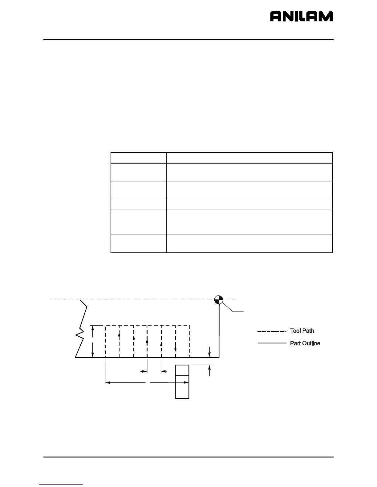
Refer to Figure 5-10. G81 creates a groove along the longitudinal (Z)
axis. Use a groove-cutting tool for this cycle. The cycle has built-in
compensation for tool width. Position the tool appropriately (with the tool
width taken into consideration) before the canned cycle begins.
W
B
X
Z
X0, Z0
Figure 5-10, G81 Address Words
Use G81 for inner diameter or outer diameter cuts. B determines the
standoff position in X, from which the tool advances to the start of the
grooving cycle.


 To Next Page