4200T CNC Programming and Operations Manual
P/N 70000412F - Canned Cycles
5-16 All rights reserved. Subject to change without notice.
31-July-05
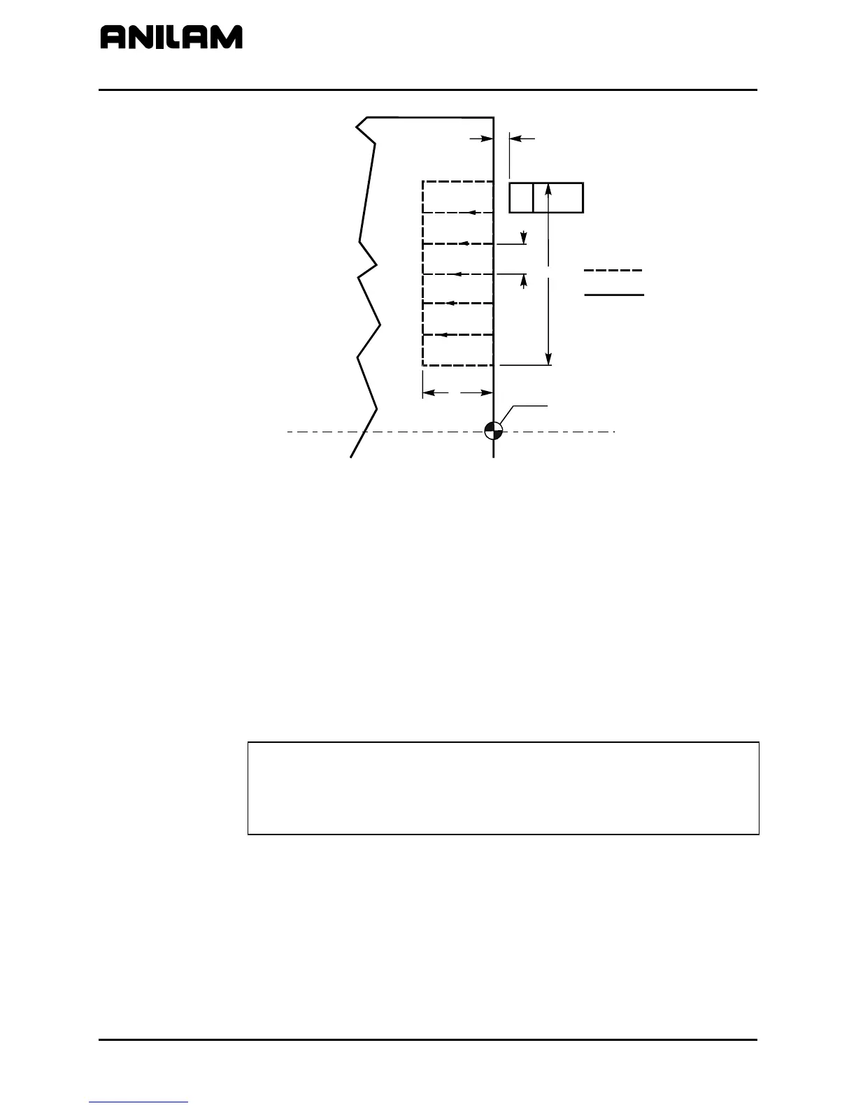
W
B
Z
X
X0, Z0
Part Outline
Tool Path
Figure 5-12, G82 Address Words
Refer to Figure 5-12. The G82 canned cycle creates a groove along the
radial (X) axis. Use a groove-cutting tool for this cycle. The cycle has
built-in compensation for tool width. Position the tool appropriately before
the cycle begins.
B determines the standoff position in Z, from which the tool advances to
the start of the grooving cycle. G82 can be used for I.D. or O.D cuts.
After the tool reaches total depth (Z), it remains at the bottom of the
groove until the dwell time (D, optional) elapses. The CNC calculates the
number and width of passes from the total length (X) required and the tool
width (W). After the cycle terminates, the CNC returns to the starting
coordinates of the cycle.
NOTE: All variables are sign (+/-) dependent. Moves can be defined as
Outer Diameter/Inner Diameter, and toward or away from the
chuck or part centerline. The positive/negative direction (sign of
the variable) determines what kind of move is made by the CNC.
Make sure to program the appropriate sign (+/-).


 To Next Page