AR5000 OPERATING MANUAL PAGE 33
(7) Memory banks & channels
It is very convenient to store commonly used frequencies
into a memory bank along with mode and attenuator
status, this saves having to key the data in over and over
again. Memory recall is very straightforward and quick
when compared to retyping all data.
Think of memory channels as pages in a notebook each
of which is numbered to identify it. Data may be written
to each new page (memory channel) and each page may
be overwritten with new data, they can be used over and
over again.
Each memory channel may hold:
w 1 One receive frequency
w 2 Receive mode
w 3 IFBW
w 4 LPF
w 5 HPF
w 6 De-emphasis
w 7 Tuning step
w 8 Step-adjust
w 9 Frequency offset
w 10 AGC
w 11 Attenuator
w 12 CTCSS tone
w 13 Aerial selection
w 14 Eight character TEXT comment
w 15 Pass (lockout) & select scan list status
The TEXT comment assists ease of identification at a
latter date and the other parameters provide great
convenience and minimise the need for extensive
reprogramming.
A total of 1000 memory channels are provided which are
divided into 10 banks, each having 100 channels. The
memory banks are identified by the first BANK number 0,
1, 2, 3, 4, 5, 6, 7, 8 & 9 and the individual channels are
numbered from 00 to 99.
Examples are “000” for the first channel location in
memory bank “0” and “099” for the last memory channel
in memory bank “0”.
“415” is the location: memory bank “4” channel “15”.
Memory bank “0” may be used as any other bank but
also has a special facility of auto-store where active
frequencies found in search mode may be automatically
entered into the 100 memory channels 000 to 099 for
later review, recall and scanning. Please refer to section
12-19 of this manual for further information regarding
AUTO-STORE.
The data contents of memory and search banks are held
in an EEPROM so that no backup battery or capacitor is
required for memory retention.
The stored data may be quickly and easily recalled,
changed or deleted using the memory recall and delete
facilities.
Note: When the receiver is switched OFF using the front
panel
key, all VFO data will be automatically stored
into EEPROM memory storage. However, should the
power be removed while the receiver is switched on (power
cut or flat vehicle battery etc), the last stored memory
channel or last VFO data
may
be lost.
During the manufacture and testing of the receiver, various
test frequencies are entered into the receiver’s memory
banks so the memory locations are unlikely to be
completely blank.
Note: Where memory banks etc are empty during
memory storage, the indication “- - - - - - - - - -” is
displayed. If an attempt is made to recall an empty
memory channel, an error bleep is sounded and the
receiver increments to the first memory channel
containing data either above or below the keyed
memory location depending upon the current
direction determined by the
and
keys.
7-1 Storing receive data into memory
- memory input in VFO mode
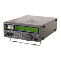
Let’s assume that you wish to store the frequency of 88.3
MHz with AUTOMODE set into memory bank “1” location
“00” (100) while in VFO mode (in this example VFO-A
is used).
Start by selecting VFO mode (by pressing the
key
until “VA” is displayed in the lower right corner of the LCD)
then key in the frequency of 88.3 MHz,
mode and step
size
are set to the default AUTO.
i.e. to place the receiver into VFO mode
to select the desired frequency,
the mode and step size will be automatically set by the
AR5000 microprocessor.
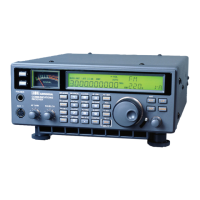
Press and hold the key for more than one second
to enter memory input mode.
The keyed frequency starts to FLASH on the LCD. To
the right of this frequency the legend “- - >” will be displayed
pointing at the first available empty memory location.
The memory location is alternatively displayed as a group
of three numbers on the right of the LCD under the flashing
“BANK” legend... the top number is the BANK and the
lower two digits the CHANNEL.
The flashing legend “M” for
memory
also indicates that a
memory location is being displayed (rather than a search