YC500A Installation/User Manual
Installation Procedures
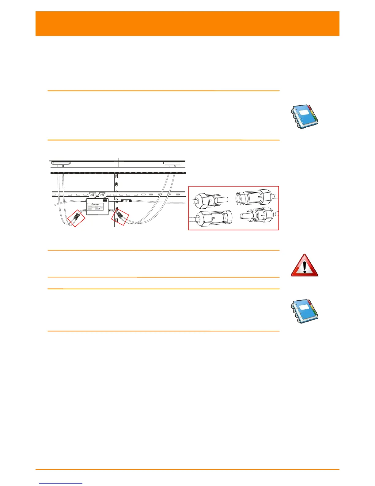
Step 4 - Connecting APsystems Microinverters to the PV Module
Connect the DC cables from the PV Modules to the Microinverter per the
diagram below:
NOTE:
When plugging in the DC cables, the Microinverter should
immediately blink green three times. This will happen as soon as
the cables are plugged in and will show that the Microinverter is
functioning correctly. This entire check function will start and end
within 5 seconds of plugging in the unit, so pay careful attention to
these lights when connecting the DC cables.
Figure 11
WARNING: Insure that all AC and DC wiring is correct. Check that
none of the AC and DC wires are pinched or damaged. Be sure that
all AC isolator are properly closed.
NOTE:
About A and B Sides corresponding the location of modules,
EMA registration show acquiesce in this installation. if there are
different connection methods, please email the detail installation
drawings to us to register, or the A, B Sides corresponding component
location will not correspond to the EMA position.