cable to the connector labeled “Interface In” on the Option 08 Linking Card on the
rear panel of the instrument that will be set up as Slave (2).
Note: APT’s SmartDetect feature will automatically configure the instruments as
master and slave depending on how the interface cable is connected. The
operator does not need to adjust any settings on the instruments’ front panel.
APT’s SmartConfig feature will automatically adjust the firmware to display the
appropriate output modes depending on the number of sources that are
interconnected.
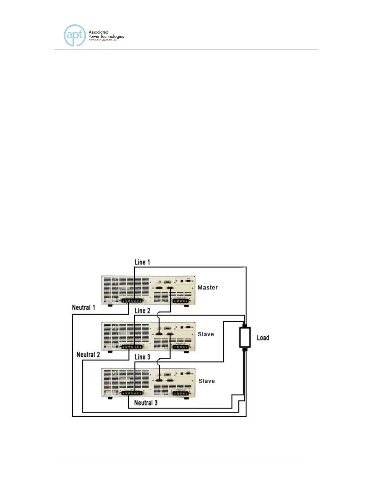
6.1.3 Output Wiring Diagrams
The following diagrams detail the correct setup for configuring multiple 300XAC
power sources to operate in Parallel and Polyphase modes. Make sure that the
instruments are OFF before attempting to make any connections.
Parallel Mode (1Φ2W)
In this condition, each instruments’ Line output must be connected together and
each instruments’ Neutral output must be connected together at the load. See
the figure below for the Parallel mode output wiring diagram: