19
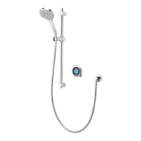
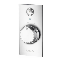
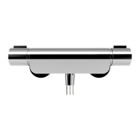
Concealed valve
The concealed Opto valve is designed for conventional supplies with HOT on the Left and COLD on the Right as viewed from the
front. However, the concealed valve can be adapted for use with reversed supplies, by adopting the following procedure.
NB The on/off knob will be upside down.
1 Ensure the temperature lever is set to the vertical position.
2 Remove the on/off knob (if fitted). Remove the four temperature control lever fixing screws and detach the lever.
3 Rotate the valve body by 180º. Remove and reposition the outlet cap as required. The valve will now be in the ‘upside down’
position.
4 Ensuring the temperature lever is in the vertical position, replace the lever and secure using the temperature screws hand tight
only.
5 Ensuring the on/off graphics are positioned at the bottom of the knob and the fin is in the vertical position when the valve is in the
off position, push the on/off knob onto the valve fully home.
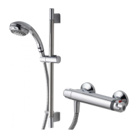
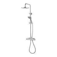
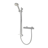
Exposed valve
The exposed Opto valve is designed for conventional supplies with HOT on the Left and COLD on the Right as viewed from the front.
However, the exposed valve can be adapted for use with reversed supplies, but it will be necessary to contact Aqualisa customer
services on 01959 560010 to purchase reversed graphics to enable this operation.
1 Remove the shrouds and cartridge assembly from the backplate as detailed on pages 11 & 12.
2 Make a note of the orientation of the settings and the position of the on/off knob before removing the fixing screw and
pulling the knob clear.
3 Rotate the cartridge assembly 180º so the H & C temperature markings on the top of the cartridge assembly are now positioned
on the bottom of the cartridge.
4 Replace the existing conventional on/off control graphic ring with the new one purchased separately.
5 Replace the control knob ensuring it is in the same position as prior to being removed.
6 Remove and rotate the outlet connection 180º to ensure it is positioned at the bottom of the valve.
7 Refit the adapted cartridge assembly to the backplate and refit the shrouds as previously instructed.
Reversed supplies
 Loading...