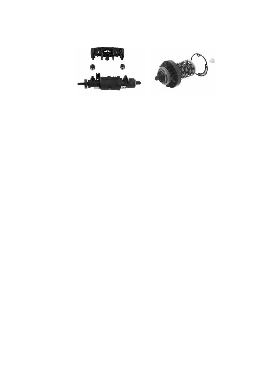
Filters
To ensure optimum ongoing performance, the ‘CARTRIDGE’ control mechanism is protected by a two part filter system in the
internal waterways. Debris accumulation may result in progressively reduced flow through the showerhead and noisy operation.
As this condition is not covered by our standard warranty terms, it is suggested that the cartridge is removed and the filters checked
by a competent person. In the event of any difficulties please contact the Aqualisa customer helpline for assistance.
Isolating valves
Suitable isolation valves such as gate valves must be fitted to both supplies in accordance with current Water Supply Regulations and
our terms of warranty. Due to their restrictive characteristics, stopcocks and ball type valves that reduce the pipe bore size must not
be used on gravity or pumped installations.
Pressures
Opto shower valves are designed to control static pressure up to 10 bar. Where pressures are likely to exceed 10 bar, a pressure
reducing valve (PRV) must be fitted into the incoming mains supply. A setting of 3 bar is recommended. It should be noted that
daytime pressures approaching 8 bar can rise above the stated maximum overnight.
Opto shower valves are not suitable for mixed supply systems e.g. Gravity hot and mains cold.
Gravity systems
Services must be installed according to good plumbing practice having regard to pipe sizing, long pipe runs and low-head situations.
The cold supply for the valve assembly must be taken directly from the cold storage system.
The hot supply may be taken from the vent/draw off pipe of the hot water cylinder at a point below the cylinder connection or
alternatively from the underside of the horizontal draw off. Rising pipe work must not be connected into the horizontal draw off from
the cylinder or to any point in the vent/draw off pipe above the cylinder connection.
CYLINDER TEMPERATURE IN EXCESS OF 65ºC MAY RESULT IN POOR SHOWER PERFORMANCE.
To minimise pressure loss we recommend that the hot and cold supplies are run in 22mm as close as reasonably possible to the
mixing valve before reducing to 15mm.
Siting
For optimum performance, with gravity fed systems, the distance between the bottom of the storage cistern and the shower head
should not be less than 1m (when using an adjustable height shower head). If using a fixed head, the highest point of the pipe work
must be not less than 1m below the underside of the cistern. Please refer to the system layout on page 20.
Pump installation
UNDER NO CIRCUMSTANCES MUST A PUMP BE FITTED DIRECTLY TO THE WATER MAIN.
A pump must only be used to boost the pressure from tank-fed supplies. A typical layout is shown on page 20.
Stored water capacities
The minimum capacity of the cold storage cistern should not be less than 225 litres (50 gallons). The capacity of the hot cylinder
must be capable of meeting the anticipated demand.
5