Page 22
Troubleshooting Controller
—
Input Status LED’s
These LEDs are only visible with the front face removed and when you can physically see the SPC circuit board.
All inputs and outputs (with the exception of AI1) on the SPC have an associated LED to help troubleshoot whether or not
there is a signal being receive or sent (respectively). This will help you to troubleshoot floats, over pressure sensor, mute
button, strobe, and sounder faults. To trouble shoot AI1, use either line 4 of the LCD screen or the “?s”, “ACD”, or “inputs”
commands via the USB interface.
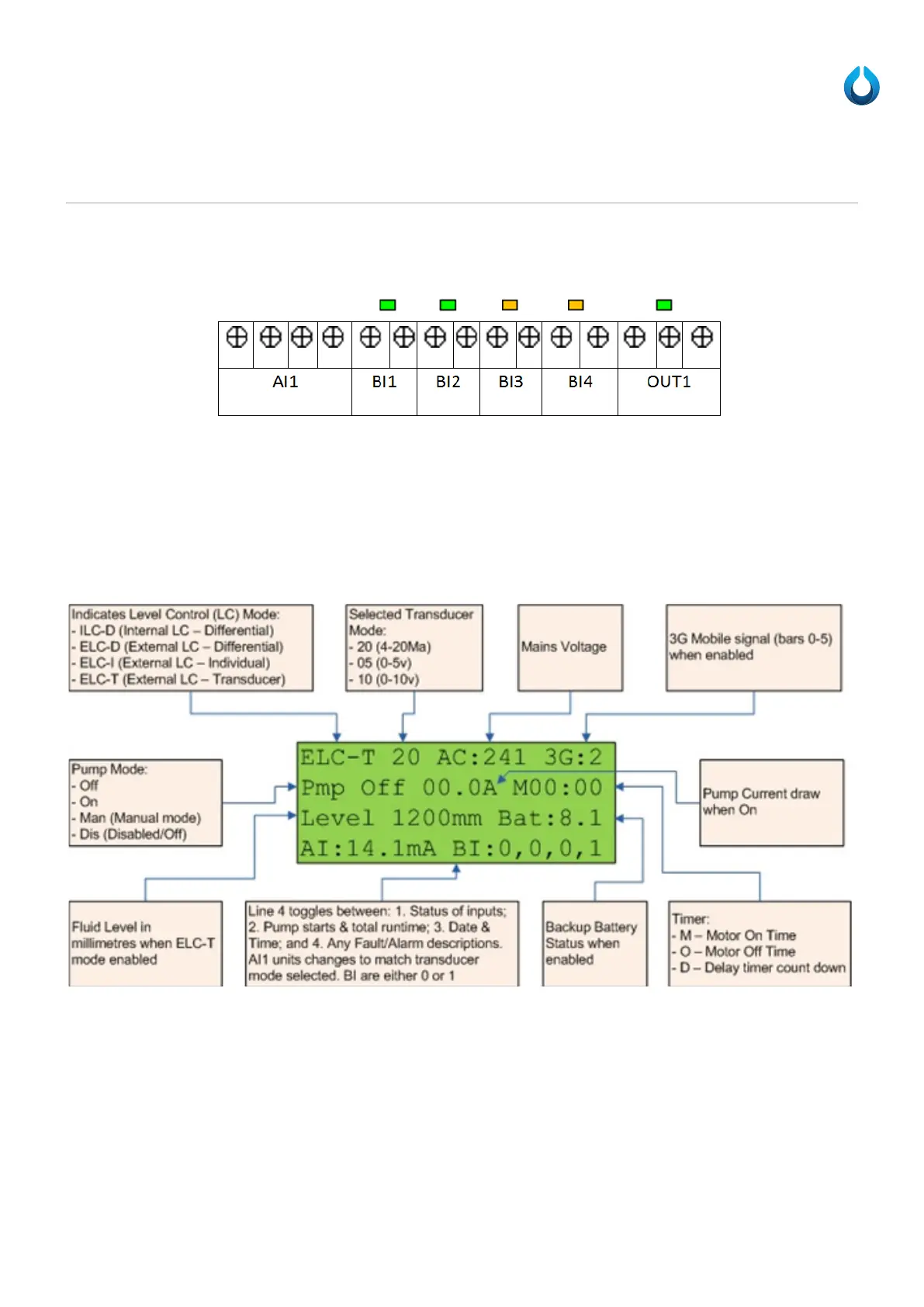
LCD (Optional Extra)
An optional extra is to include a 4 line by 20 character per line LCD, displaying the following:
Line 4 of the LCD toggles between:
1. Status of inputs (shown above)
a. AI1 units changes to match transducer mode selected.
i. i.e. Milliamps (mA) or Volts (V)
b. BI(1-4) are either 0 or 1
2. Pump starts (TotalMotorStarts) & total runtime (TotalRunTime), and
a. ST:00000 RUN:HHHH:MM
3. Current Date and Time
4. Any current Alarm descriptions.
a. If there is more than one alarm then it will toggle through these before starting back to status of inputs.