5-3
5
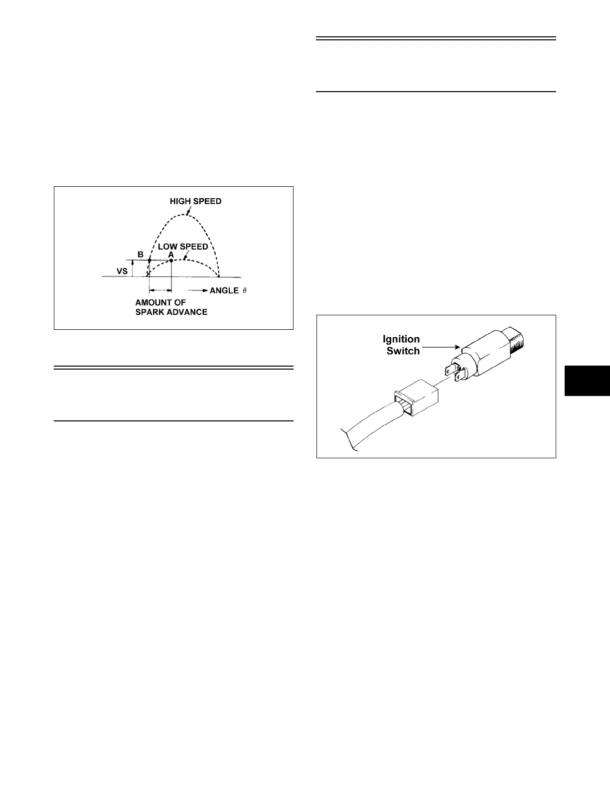
SPARK ADVANCE
CHARACTERISTIC
As noted above, the unit circuit detects a voltage and
makes switching to produce a high voltage required to
produce a spark. On the other hand, the wave form of
the voltage generated in the primary winding changes
as the flywheel turns.
The working voltage (VS) of the unit circuit is at level
A when the engine is started, but as the engine speed
increases, the wave form of the voltage changes and
advances to level B.
GEN-0009
Troubleshooting
Ignition System
(120 cc)
1. Remove the spark plug and visually check its
condition. Replace if fouled. Adjust spark plug
gap to 0.7 mm (0.028 in.). Attach the high tension
lead to the spark plug and ground the plug on the
cylinder head.
NOTE: Make sure the emergency stop switch is
in the ON (UP) position, the ignition switch is in the
RUN position, and the tether cord is connected to
the tether switch.
2. Crank the engine over and check for a spark. If no
spark is present, disconnect the main wiring
harness from the engine. Crank the engine over. If
spark is now present, the problem is either one or
more of the following items.
A. Defective ignition switch
B. Defective emergency stop switch
C. Defective wiring harness
D. Defective tether
Testing Main Wiring
Harness
(120 cc)
NOTE: The main wiring harness test can be
made using the Fluke Model 73 Multimeter (p/n
0644-191).
1. Disconnect the engine wires from the main wiring
harness.
2. At the main wiring harness engine connector,
connect the red tester lead to the violet wire; then
connect the black tester lead to the engine ground
(brown wire).
3. With the ignition switch in the RUN position, the
emergency stop switch in the ON position, and the
tether cord connected, the meter must read no
resistance. If the meter reads resistance,
disconnect the ignition switch from the main
wiring harness. If the meter now reads no
resistance, replace the ignition switch.
725-704A
4. If the meter continues to read resistance with the
ignition switch disconnected, disconnect the
emergency stop switch. If the meter now reads no
resistance, replace the emergency stop switch.
5. If the meter continues to read resistance with both
the ignition switch and the emergency stop switch
disconnected, disconnect the wires to the tether
switch. If the meter now reads no resistance,
replace the tether switch.
6. If the meter continues to read resistance with all
three switches disconnected, replace the main
wiring harness.