2-28
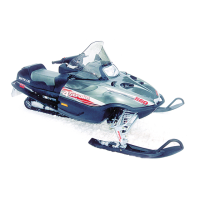
35. Push the piston/connecting rod assembly out
through the top of the cylinder bore. Repeat for the
remaining two piston/connecting rod assemblies.
MD1539
36. For assembling purposes, take note that the arrow
on each piston points toward the timing cover side
of the engine; then number the dome of each
piston starting from the timing cover side. Remove
the timing cover side circlip from each piston.
37. Using Piston Pin Puller (p/n 0644-328), remove
the piston pin from each piston.
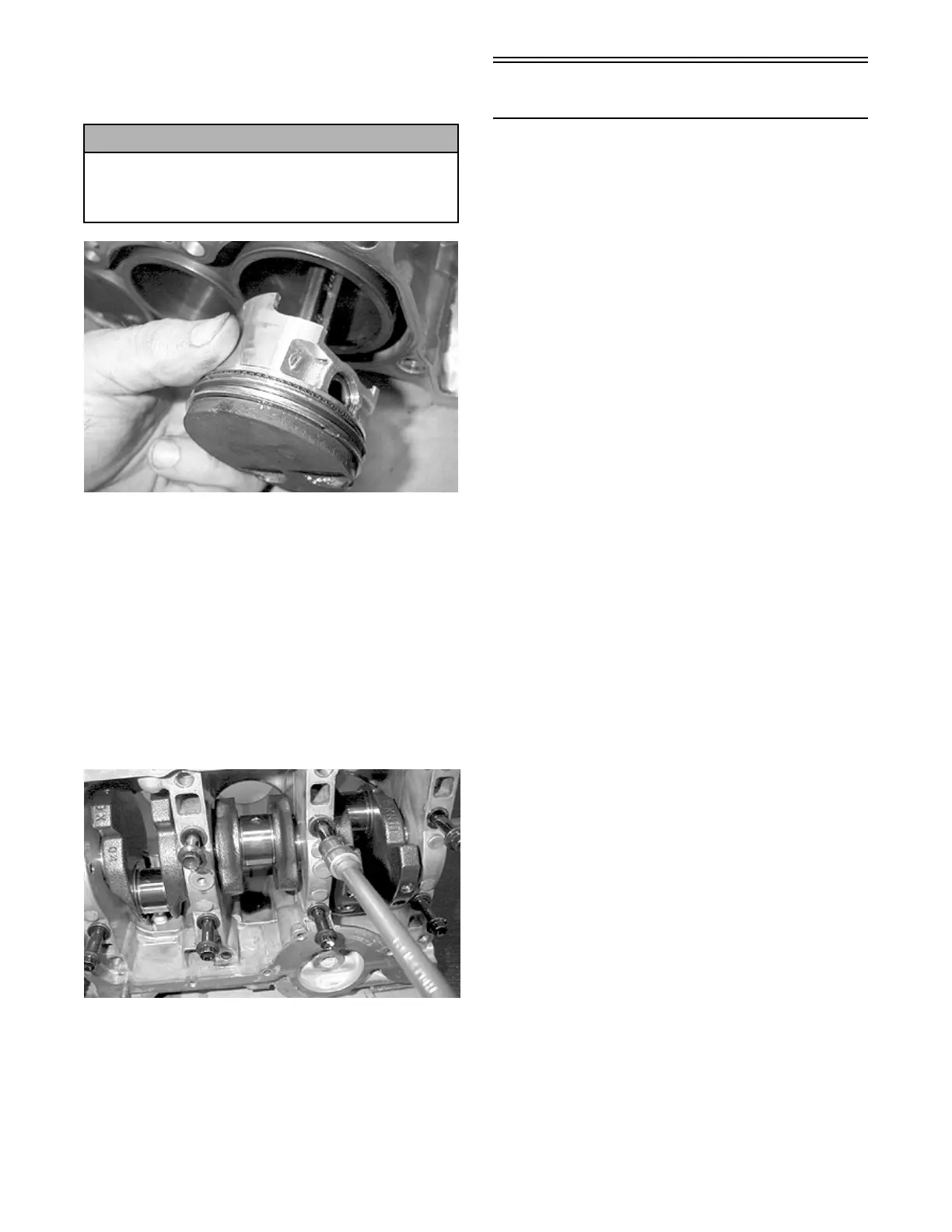
38. Remove the inner and outer cap screws
securing the lower crankcase half to the upper
crankcase half; then separate the crankcase halves.
Account for four dowel pins, eight crankshaft
bearings, and two thrust washer halves.
MD1549
39. Remove the crankshaft. Account for the remaining
crankshaft bearings.
Servicing Components
(120 cc Model)
NOTE: Critical engine specifications are located
at the beginning of this section.
Thoroughly clean all non-electrical components in
parts-cleaning solvent; then remove any carbon
buildup from the cylinder head, piston dome, valves,
and valve seats.
Visually inspect all engine components for wear or
damage.
NOTE: Whenever a part is worn excessively,
cracked, or damaged in any way, replacement is
necessary.
CYLINDER HEAD/VALVE ASSEMBLY
NOTE: Remove the valves by pressing down on
the spring retainer and removing the valve keeper.
Account for valve springs, spring retainers, and
valve keepers.
When servicing valve assembly, inspect valve seats,
valve stems, valve faces, and valve stem ends for pits,
burn marks, or other signs of abnormal wear.
NOTE: Discard any valve that fails the listed
inspections. Do not grind the valves. If a valve is
damaged, it must be replaced.
Measuring Cylinder Head Distortion
1. Using a non-metallic carbon removal tool, remove
any carbon buildup from the combustion chambers
being careful not to nick, scrape, or damage the
combustion chambers or the sealing surfaces.
2. Inspect the spark-plug holes for any damaged
threads. Repair damaged threads using a heli-coil
insert.
3. Inspect the cylinder head for flatness using a
straightedge and a feeler gauge. Acceptable
distortion must not exceed specifications.
NOTE: If the distortion exceeds specification,
replace the cylinder head.
Measuring Valve Stem Runout
1. Support each valve stem end with V Blocks (p/n
0644-022); then check the valve stem runout using
a dial indicator.
! CAUTION
Install two lengths of gasline hose approximately
12.7 cm (5 in.) long onto the connecting rod
studs to avoid damaging the crankshaft journals
and cylinder walls.
 Loading...