2-29
2
ATV-1082
2. Maximum runout must not exceed specifications
for both valves.
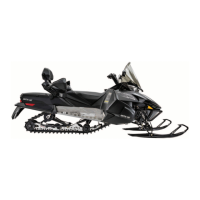
Measuring Valve Face Width
1. Using a micrometer, measure the width of the
valve face.
ATV-1004
2. Acceptable valve face width must be within
specifications.
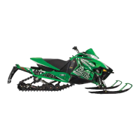
Measuring Valve Face Runout
1. Mount a dial indicator on a surface plate; then
place the valve stem on a set of V blocks.
2. Position the dial indicator contact point on the
outside edge of the valve face; then zero the
indicator.
ATV1082A
3. Rotate the valve in the V blocks.
4. Maximum runout must not exceed specifications.
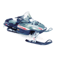
Replacing Valve Guide
NOTE: If a valve guide is worn or damaged, it
must be replaced.
1. If a valve guide needs replacing, before removing
the existing guide, measure the distance from the
top of the valve seat to the top of the valve guide
(B) for a reference depth when installing the new
guide.
GEN-0021
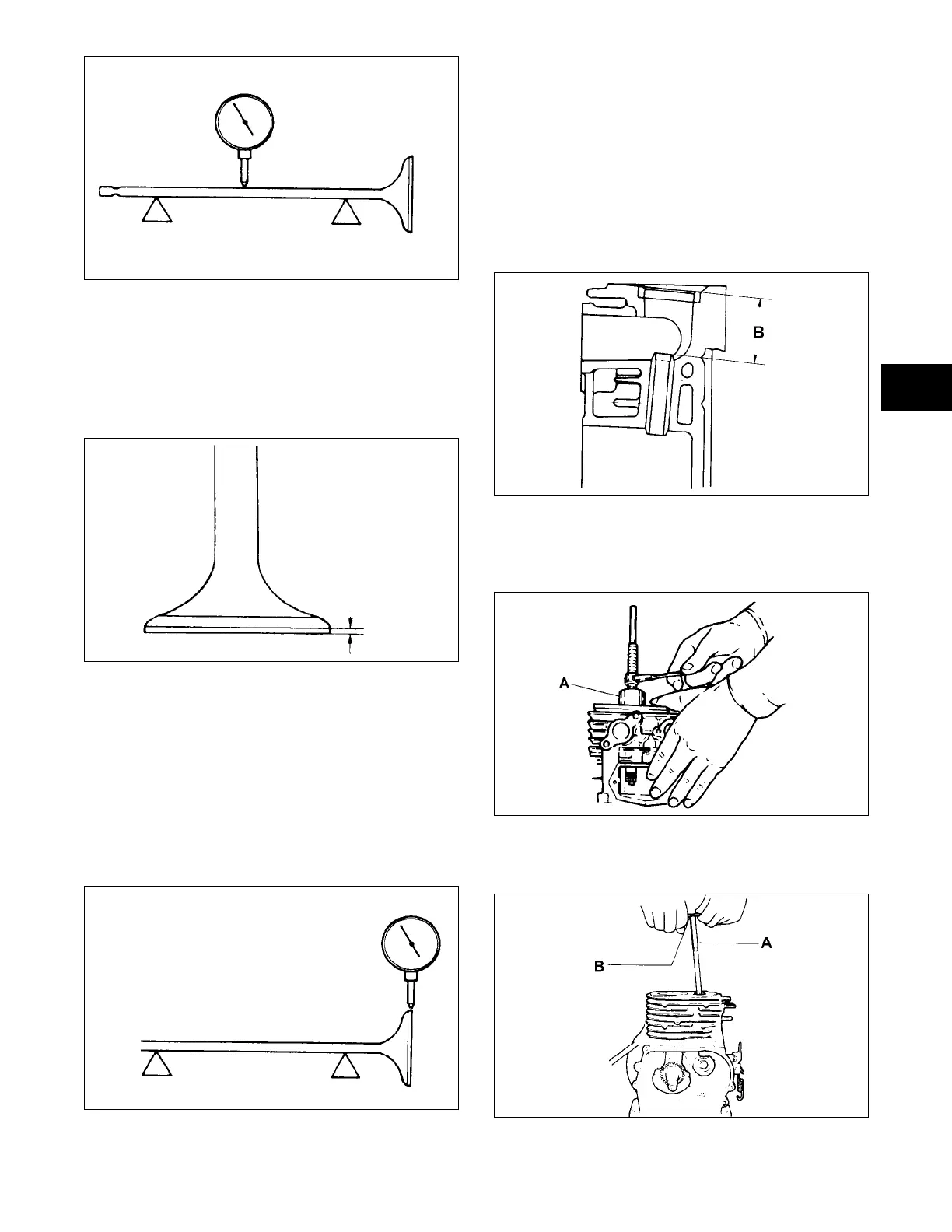
2. To replace a valve guide, use a valve guide
remover from the top side of the cylinder to gently
pull the valve guide out of the cylinder.
GEN-0017
3. Using a valve guide reamer, remove any burrs or
tight areas from the valve guide journals.
GEN-0018
 Loading...