69
NOTE: For assembling purposes, lubricate the rub-
ber side of the washer before installing.
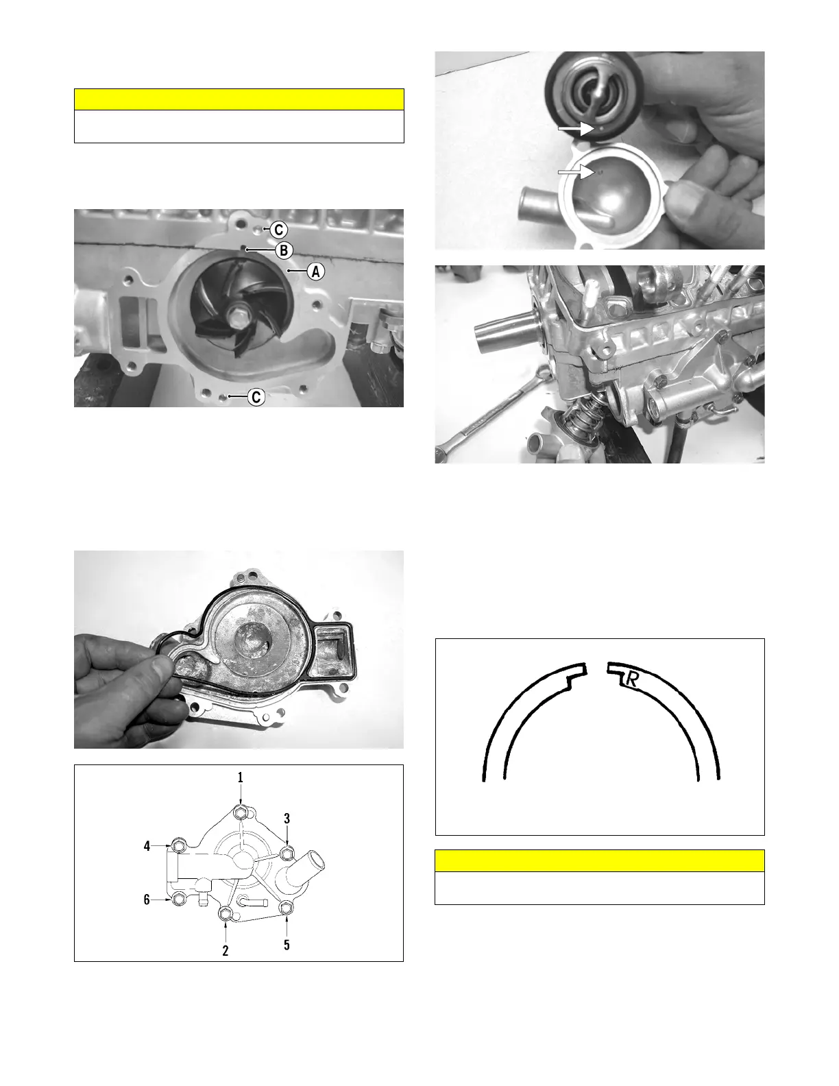
20. Apply High-Temp Sealant to the crankcase/water
pump cover seam (A); then install the dowel pins (C)
into the crankcase.
FC072C
NOTE: Do not allow sealant into the breather hole
(B) in the crankcase. If sealant gets into the hole, care-
fully remove before proceeding.
21. Position the O-ring (lightly coated with oil) into the
water pump cover; then install the cover. Secure with
six screws; then using the pattern shown, tighten to
96 in.-lb.
FC134
0742-304
22. Noting the alignment dots, install the thermostat
housing with thermostat. Secure the housing with
cap screws and tighten to 96 in.-lb.
FC078A
FC073
23. With new gaskets, install the reed valve assemblies;
then secure the intake flanges to the crankcase.
Tighten in a crisscross pattern to 96 in.-lb.
24. Install the dowel pins into the crankcase; then place
the cylinder base gasket into position on the crank-
case.
25. Install the piston rings on each piston so the letter on
the top (inclined surface) of each ring faces the dome
of the piston.
726-306A
26. Apply oil to the connecting-rod small end bearings;
then install the small-end bearings. Install a washer
on each side of the connecting rod.
CAUTION
If the rubber side of the washer is not positioned toward
the impeller, a coolant leak will result.
CAUTION
Incorrect installation of the piston rings will result in
engine damage.
 Loading...