88
CM142A
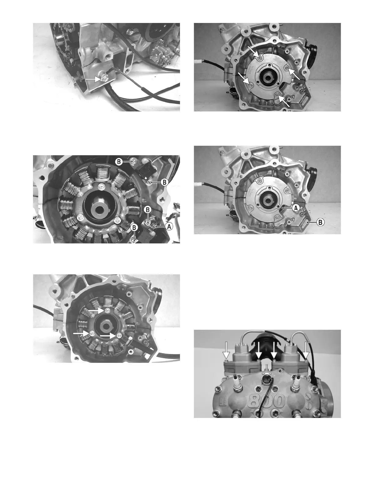
5. Remove the Allen-head cap screw (A) securing the
stator lead wire plate to the crankcase; then remove
the Allen-head cap screws (B) securing the timing
sensors, remove the sensors, and account for the har-
ness grommets.
CM141C
6. Remove the Allen-head cap screws securing the sta-
tor to the stator plate. Route the stator lead wire out
of the crankcase; then remove the stator assembly.
CM143A
7. Remove the cap screws securing the stator plate to
the engine; then remove the plate.
CM145D
NOTE: For assembling purposes, note the indenta-
tion (A) of the stator plate is aligned with the harness
opening (B) in the crankcase.
CM145C
NOTE: The stator plate screws had Loctite applied
to the threads during assembly. Using an impact
driver, apply a sharp blow to the head of each screw
to break the Loctite loose before removal.
8. Remove the cap screws securing the APV assemblies
to the cylinders; then remove the APV assemblies
and set them aside.
NOTE: For assembling purposes, note that the APV
exhaust valves and gaskets are directional and
marked (M) for magneto cylinder and (P) for PTO
cylinder.
XM024A
 Loading...