48
E-119TRI+DISC 345A / 345B: ASSEMBLY GUIDE
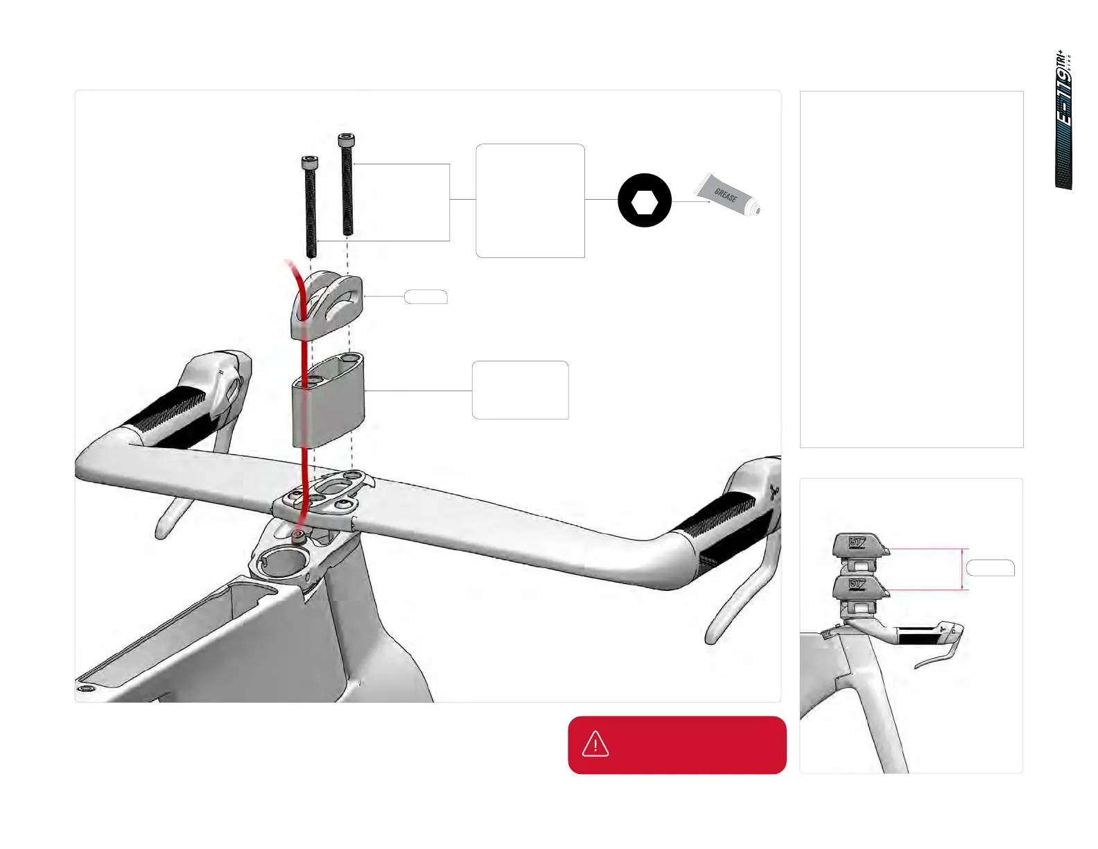
14.1 Cockpit assembly
81525
81526 - 5mm
81526 - 10mm
81526 - 20mm
81526 - 40mm
81526 - 70mm
4
6Nm
2.5
1Nm
4
5.5Nm
4
7Nm
2
HT-1/4
5
12Nm
2
2Nm
3
3Nm
4
3Nm
8
35Nm
2.5
HT
3
HT
40Nm
4Nm
T25
T25
4
3Nm
10
HT
2.5
5
9Nm
2.5
HT-2
2.5
HT-5
2.5
2Nm
3
2.5
HTHT
3
4Nm
3
2Nm
6
10Nm
2.5
HT
4Nm6Nm
8
81532 - M6 x 30mm
81533 - M6 x 40mm
81534 - M6 x 50mm
81535 - M6 x 60mm
81536 - M6 x 70mm
81537 - M6 x 80mm
81538 - M6 x 90mm
81539 - M6 x 100mm
81540 - M6 x 110mm
81541 - M6 x 120mm
1. Choose the right combination of
spacers and screws to achieve
the desired fit. See next page for
stack configuration options.
2. Stack the spacer(s) onto the first
spacer. Each spacer will clip on
the lower one.
3. Set the swivel (SKU: 81525) on top
of the spacer or spacers stack.
4. Apply grease to the threads of the
two spacer screws (SKU: 81532
to 81541).
5. Install and tighten both M6
spacer screws to 6 Nm.
6. Note: For a Di2 assembly, run
the Di2 extension cable from the
junction box through the channel
in the spacers and swivel.
IMPORTANT:
90 mm spacers max.
90mm