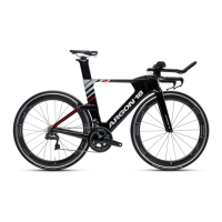
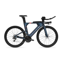
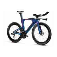
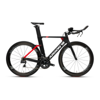
Do you have a question about the Argon 18 E-119 TRI+ and is the answer not in the manual?
Lists all spare parts and their SKU numbers with diagrams for easy identification.
Detailed list of frameset parts, their associated SKU numbers, and quantities required.
Instructions for assembling the seat post, including torque values and adjustments.
Details on how to assemble the seat post collar, including grease and threadlocker application.
Guidelines for seat post height limits and cutting, with diagrams.
Procedures for adjusting the rear derailleur hanger with threadlocker and torque.
Steps for assembling the front derailleur hanger for single or double chainrings.
Initial steps for fork and headset assembly, including grease application.
Installation of top and bottom bearings for the fork and headset.
Finalizing fork and headset assembly with specific tools and torque.
Instructions for routing and attaching the front brake caliper to the fork.
Steps for routing and attaching the rear brake caliper to the chainstay.
Installation of the rear brake cover and securing it with screws.
General overview of DI2 cable routing paths on the frame.
Specific routing instructions for rear and front derailleur DI2 cables.
Installing the EW-RS910 junction box and door frame receptacle.
Routing DI2 cables and brake hoses through the handlebar.
Connecting DI2 cables to the junction box and installing the handlebar.
Overview of cable routing for eTap systems on the frame.
Specific grommet installation for rear and front derailleur eTap cables.
Installing the door frame receptacle for eTap cable management.
Routing eTap shifter cables and brake hoses through the handlebar.
Installing the handlebar and securing brake housings for eTap.
General routing for mechanical cables on the frame.
Routing mechanical derailleur cables through the frame.
Installing the door frame receptacle for mechanical cable management.
Routing mechanical brake hoses through the handlebar.
Installing the handlebar and securing brake housings for mechanical setup.
Preparing the brake lever wedge assembly with grease and screws.
Adapting brake levers for DI2 shifting, including cable tie use.
Adapting brake levers for eTap shifting with SRAM adapters.
Adapting brake levers for mechanical shifting with blank adapters.
Inserting brake lever handles for mechanical, Di2, or eTap builds.
Cutting hydraulic brake hoses to specific lengths for front and rear.
Installing TRP barb, olive, and compression nut for hydraulic hose connection.
Connecting electronic shifter wires and securing brake levers to the handlebar.
Selecting and stacking spacers and screws for desired cockpit height.
Guide to choosing specific spacer and screw lengths based on stack height.
Installing the bridge and adjusting its angle for cockpit setup.
Marking and cutting extensions for electronic or mechanical routing.
Diagram showing extension insert, cutting, and clamping zones.
Overview of DI2 cable routing through the cockpit components.
Overview of eTap cable routing through the cockpit components.
Overview of mechanical cable routing through the cockpit components.
Detailed routing of Di2 and eTap cables through extensions and bridge.
Routing mechanical cables through extensions and bridge.
Attaching armrests to the bridge with Velcro and screws.
Installing stem caps and blipbox for eTap systems.
Lists the components included in the bike's toolbox kit.
Instructions for installing the integrated toolbox door on the frame.
Steps for installing the rear disc rotor and wheel with torque values.
Instructions for mounting brake calipers onto the wheel rotor and frame.
Detailed step-by-step guide for bleeding hydraulic brakes.
Instructions for replacing brake pads and initial bedding-in.
Procedure for bedding in new brake pads and rotors for optimal performance.
Links to online resources for further technical information and FAQs.
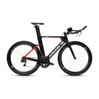
| Frame Material | Carbon |
|---|---|
| Bottom Bracket | BB86 |
| Chain | Shimano Ultegra |
| Brakes | TRP |
| Shifters | Shimano Di2 |
| Front Derailleur | Shimano Ultegra |
| Rear Derailleur | Shimano Ultegra |
| Crankset | Shimano Ultegra |
| Cassette | Shimano Ultegra |
| Tires | Vittoria |
| Handlebar | Argon 18 |
| Stem | Argon 18 |
| Saddle | ISM |
| Seatpost | Argon 18 |
| Drivetrain | Shimano Ultegra |

