51
14.4.1 Cockpit assembly - Extension Assembly
4
6Nm
2.5
1Nm
4
5.5Nm
4
7Nm
2
HT-1/4
5
12Nm
2
2Nm
3
3Nm
4
3Nm
8
35Nm
2.5
HT
3
HT
40Nm
4Nm
T25
T25
4
3Nm
10
HT
2.5
5
9Nm
2.5
HT-2
2.5
HT-5
2.5
2Nm
3
2.5
HTHT
3
4Nm
M5x 14mm
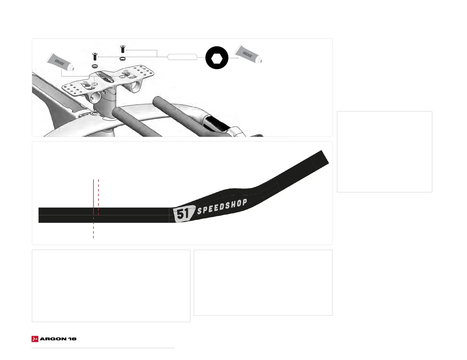
Mechanical:
1. Using a utility pick, mark the junction between the
extension and the bridge on the outside of the bridge.
2. Cut the extension on the mark made in the
previous step.
3. Make sure you're in the area for cutting and clamping
section shown on the extension.
Electronic:
1. Using a utility pick, mark the junction between the extension
and the rear face of the bridge.
2. Cut the extension 4 mm shorter than the mark made in the
previous step. (To allow space for the extensions plugs)
(See p.56)
3. Make sure you're in the area for cutting and clamping section
shown on the extension.
1. Slide both extensions into
the bridge.
2. Once the desired length is
achieved, follow the next steps
depending on the groupset used.
3. Apply grease to the threads of the
two M5 x 14 mm screws and both
sides of the spherical washers.
4. Tighten both M5 x 14 mm screws
to 4 Nm.
Electronic
Cut line -4mm
Electronic
Mark line
Mechanical
Mark & Cut Line
 Loading...