50
E-119TRI+DISC 345A / 345B: ASSEMBLY GUIDE
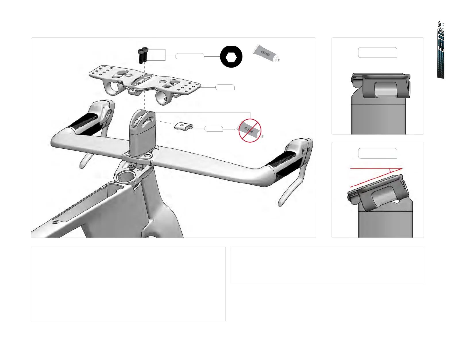
14.3 Cockpit assembly - Bridge installation
1. Slide the swivel bean (SKU: 81524) into the swivel spacer with the arrow point-
ing forward. Make sure all surfaces are free of grease.
2. For Di2 assembly, run the Di2 extension cable through the lower hole on the
bridge (SKU: 81519) and out the rear hole.
3. Apply grease to the threads of the two M6 x 30 mm screws.
4. Position the bridge on top of the swivel spacer, making sure all the pivoting
urfaces are free of grease.
5. Hand-tighten both M6 x 30 mm screws into the Swivel bean.
6. Adjust to desired angle. The bridge angle can be fixed anywhere between 0° to
20°. Follow the laser etching on the swivel spacer NDS.
7. Tighten both M6 x 30 mm screws to 9 Nm.
4
6Nm
2.5
1Nm
4
5.5Nm
4
7Nm
2
HT-1/4
5
12Nm
2
2Nm
3
3Nm
4
3Nm
8
35Nm
2.5
HT
3
HT
40Nm
4Nm
T25
T25
4
3Nm
10
HT
2.5
5
9Nm
2.5
HT-2
2.5
HT-5
2.5
2Nm
3
2.5
HTHT
3
4Nm
3
2Nm
6
10Nm
2.5
HT
4Nm6Nm
8
M6 x 18mm
81524
81519
Maximum angle
20°
Minimum angle
0°